Vacuum attachment for converting a standard vacuum into a centralized dust collection system

a vacuum and vacuum attachment technology, applied in the direction of vehicle maintenance, vehicle cleaning, cleaning equipment, etc., can solve the problems of not providing a device, collecting often becomes expensive and cumbersome, etc., and achieve the effect of convenient and economical manufacturing

Inactive Publication Date: 2006-03-02
VAN NORDEN BYRON T
View PDF11 Cites 3 Cited by
  • Summary
  • Abstract
  • Description
  • Claims
  • Application Information

AI Technical Summary

Benefits of technology

[0010] A further object of this invention is to provide a vacuum attachment, as aforesaid, that is easily and economically manufactured.
[0011] A still further object of this invention is to provide a vacuum attachment, as aforesaid, that prevents large debris from entering the attached vacuum.

Problems solved by technology

However, this collection often becomes expensive and cumbersome due to the multiple vacuums currently being used at each single location.
Indeed, power tools currently utilize independent dust collection systems that are large and heavy.
Although assumably effective for their intended purposes, the existing devices do not provide a device that allows a single standard vacuum to operate multiple vacuum lines either concurrently or at different times, allows multiple vacuum lines to be easily interchanged, securely attaches to vacuum lines, and automatically compensates for any vacuum lines that are not attached to the device.

Method used


Image

  • Vacuum attachment for converting a standard vacuum into a centralized dust collection system
  • Vacuum attachment for converting a standard vacuum into a centralized dust collection system
  • Vacuum attachment for converting a standard vacuum into a centralized dust collection system

Examples


Embodiment Construction

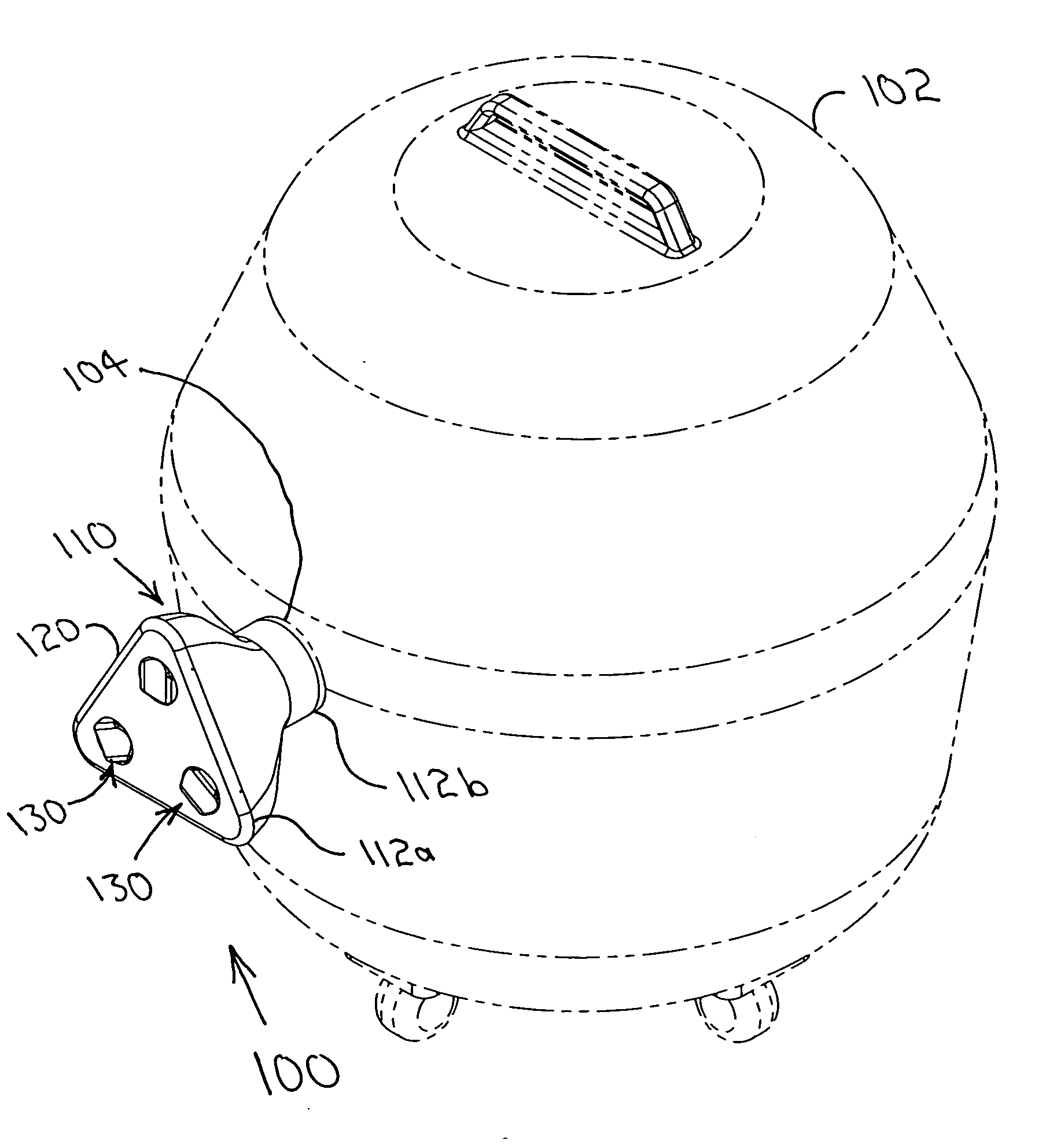
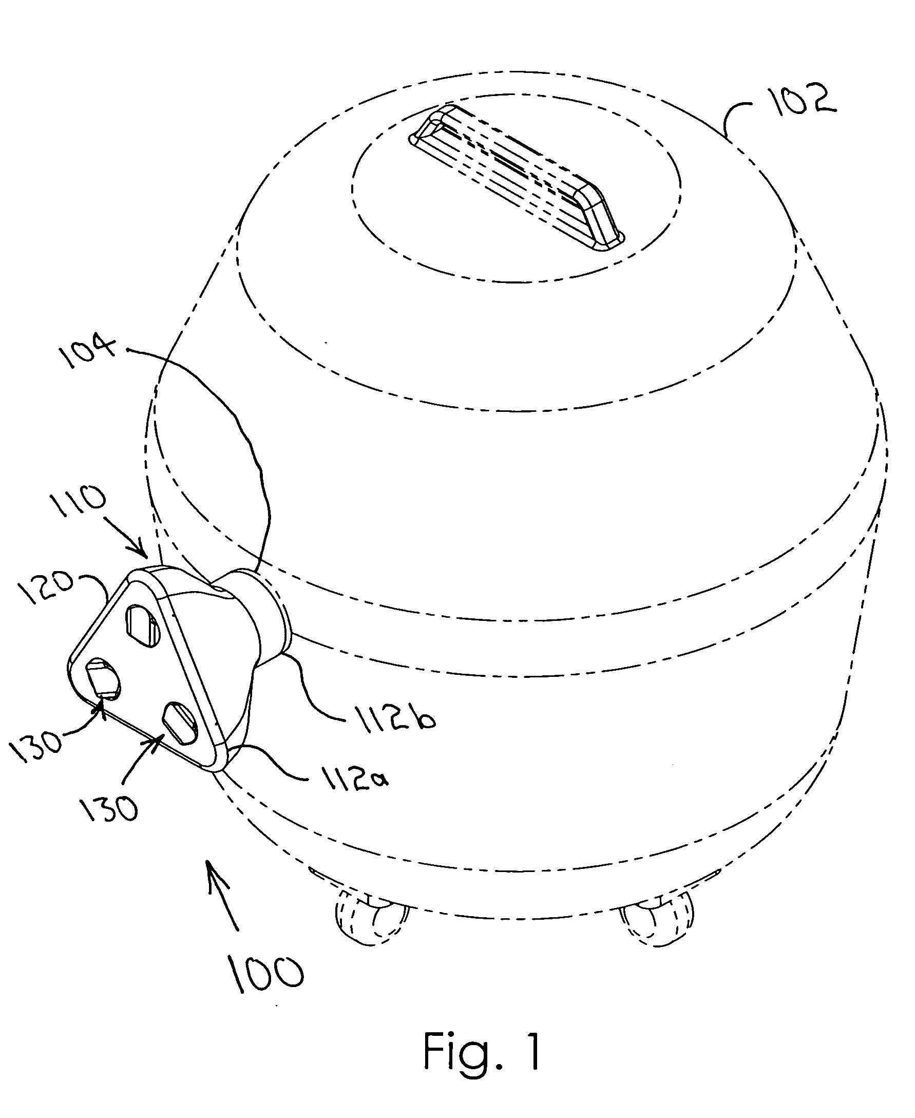
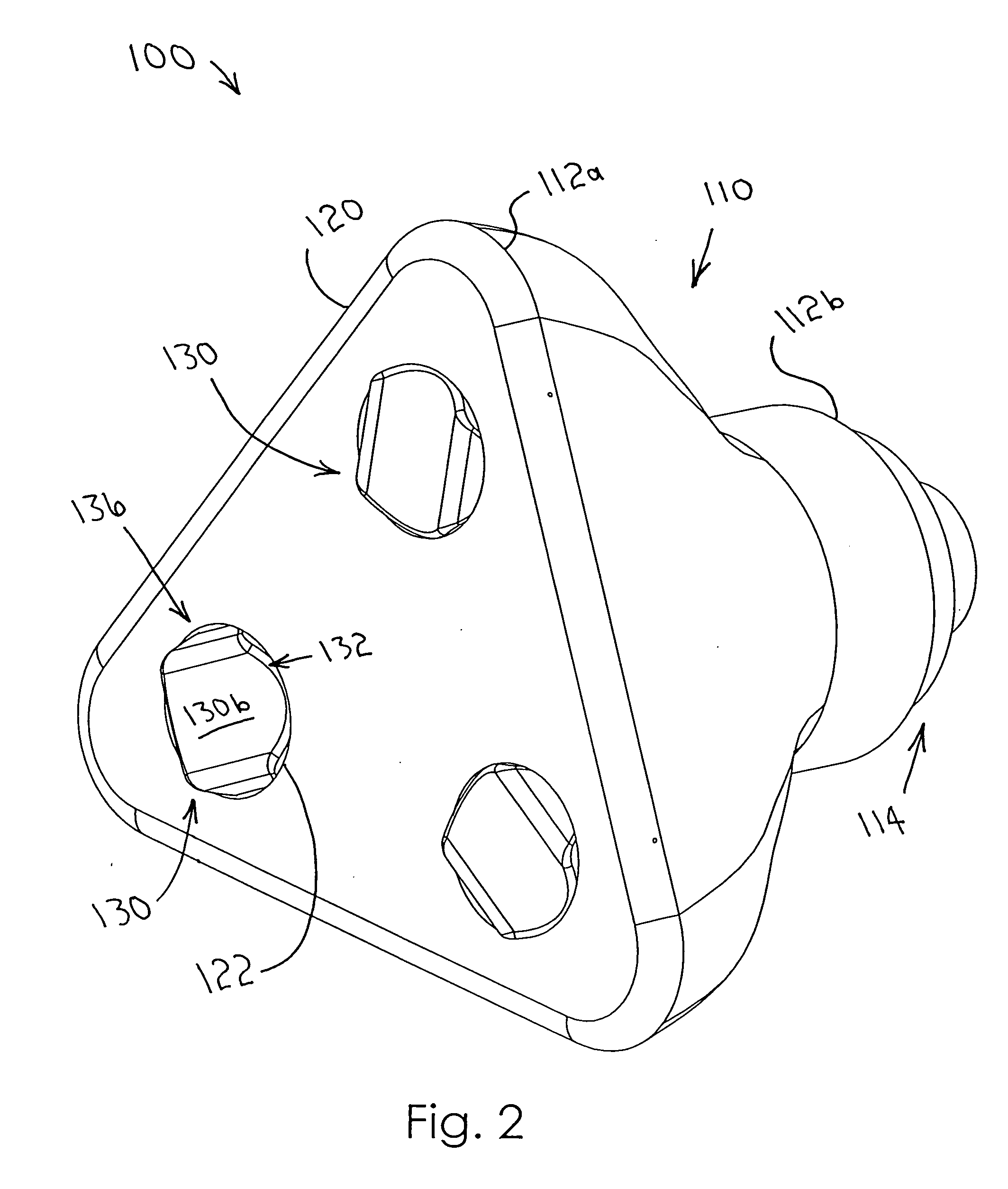
[0023] A vacuum attachment for use with a standard vacuum cleaner having an inlet port according to the present invention will now be described in detail with reference to FIGS. 1 through 4c of the accompanying drawings. More particularly, a vacuum attachment 100 includes an aerodynamic bell housing 110, a distribution plate 120 defining a plurality of blast gate openings 122, a plurality of blast gates 130, and means 140 for biasing each blast gate 130 toward a closed configuration 136 (FIGS. 2 and 4b).

[0024] The aerodynamic bell housing 110 has first and second ends 112a, 112b. The first end 112a of the bell housing 110 defines an opening 115 (FIG. 5a). The second end 112b of the bell housing 110 defines a bell housing outlet 113 and includes a standard configuration 114 (also called standard coupling means 114) for releasably coupling the bell housing 110 to an inlet port 104 of a standard vacuum cleaner 102 (FIGS. 4b and 4c). The bell housing 110 is preferably constructed of in...


PUM


Abstract

A vacuum attachment includes an aerodynamic bell housing, a distribution plate defining blast gate openings, blast gates, and means for biasing each gate toward a closed configuration. The plate attaches to the housing's first end. The gates attach to the plate for selectively covering the gate openings. An outer face of each gate includes an indented configuration. Gate openings may include internal threads. A filter may be positioned in the housing. The housing attaches to the vacuum's inlet port. Vacuum lines are inserted in the gate openings, moving the gates from closed to open configurations. The lines are locked into place by the gates' configurations and biasing means, and attached lines operate concurrently. Size and arrangement of the gate openings maintain the vacuum's airflow velocity and optimal flow patterns. To remove a line, it is withdrawn from the respective gate opening. The biasing means then automatically closes the corresponding gate.

Description

BACKGROUND OF THE INVENTION [0001] This invention relates generally to a dust collection device. In particular, the present invention relates to a vacuum attachment that allows multiple tools to utilize a single vacuum source, effectively converting a standard vacuum into a centralized dust collection system. [0002] Dust collection has made construction and building-related fields much healthier in recent years. However, this collection often becomes expensive and cumbersome due to the multiple vacuums currently being used at each single location. Indeed, power tools currently utilize independent dust collection systems that are large and heavy. Reducing the current bulk would allow more space for other tools and equipment as well as produce cost savings. [0003] Various devices have been proposed for altering the traditional vacuum design. Although assumably effective for their intended purposes, the existing devices do not provide a device that allows a single standard vacuum to op...

Claims


Application Information

Patent Timeline
Patent Type & Authority Applications(United States)
IPC IPC(8): A47L5/38
CPCA47L9/104A47L9/248A47L9/242
Inventor VAN NORDEN, BYRON T.
Owner VAN NORDEN BYRON T
Why Eureka
Try Eureka