LED lighting unit and vehicle lamp

a technology for led lighting and vehicle lights, which is applied in the direction of lighting and heating apparatus, lighting support devices, instruments, etc., can solve the problems of difficulty in conforming to the light distribution standard of vehicle lights, difficulty in flat panel display conformance,

Inactive Publication Date: 2010-02-02
STANLEY ELECTRIC CO LTD
View PDF4 Cites 22 Cited by
  • Summary
  • Abstract
  • Description
  • Claims
  • Application Information

AI Technical Summary

Benefits of technology

[0017]Moreover, the light distribution forming on the reflector of the bend portion can be adjusted by changing a reflecting angle of the bend portion. The uniformity of the above-described light distribution illuminated from the other flat surface of the light guide can be also improved by increasing a diffusing intensity of the number of light diffusing patterns on the one flat surface sequentially from the one end surface towards the other end surface and thinning a thickness of the light guide from the one end surface towards the other end surface.
[0020]According to another aspect of the disclosed subject matter, the vehicle lamp can become as thin as both thickness of the light guide and the reflection board. Thus, the vehicle lamp can expand a possibility of design thereof.

Problems solved by technology

In this case, because each of the plurality of LEDs possesses characteristics of an approximately point light source, both direct light emitted from the plurality of LEDs and indirect light reflected from the reflector form a light distribution so as to scatter each projection image of a plurality of point light sources on the front lens and therefore resulting in an irregularity of brightness.
However, it is difficult for the flat panel display to conform to a light distribution standard for a vehicle lamp and / or to function as an LED lighting unit that is mounted in a vehicle lamp.
Specifically, the flat panel display has two characteristics that make it difficult to conform to a light distribution standard for vehicle lights.
The other characteristic is a brightness characteristic that makes it difficult to meet brightness requirements or standard at each of the measuring points.
However, because the number of LEDs is limited to a size of a light guide that is limited to a size of a vehicle lamp, the above-described problem may not be practically resolved.

Method used


Image

  • LED lighting unit and vehicle lamp
  • LED lighting unit and vehicle lamp
  • LED lighting unit and vehicle lamp

Examples


Embodiment Construction

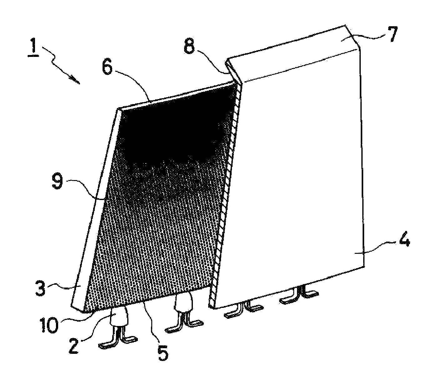
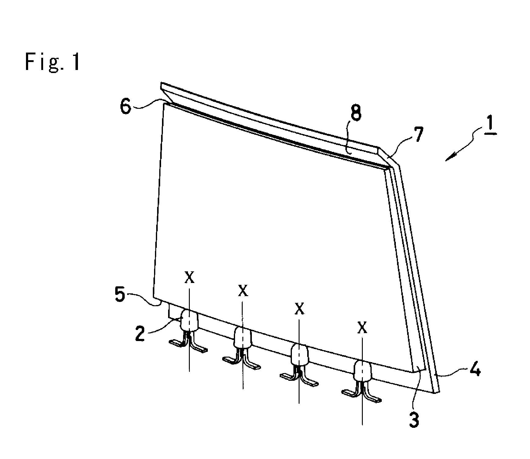
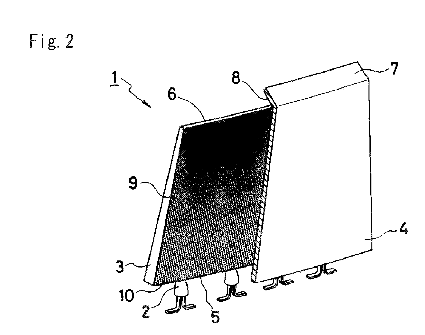
[0032]The disclosed subject matter will now be described in detail with reference to FIGS. 1 to 9. The same or corresponding elements as shown with reference to FIGS. 1 to 9 use the same reference marks. FIG. 1 is a perspective view showing an example of an LED lighting unit made in accordance with principles of the disclosed subject matter and FIG. 2 is a partial perspective view from the opposite direction of the LED lighting unit shown in FIG. 1.

[0033]As shown, an LED lighting unit 1 can be composed of a plurality of LEDs 2 configured for use as a light source, a light guide 3 and a reflection board 4 as described in detail later. Each of the plurality of LEDs 2 can be a dome-shaped LED encapsulating an LED chip with a transparent resin and can be disposed at a substantially equal interval so that each optical axis thereof is parallel with respect to each other.

[0034]The light guide 3 can be composed of a transparent material and formed in a flat shape. However, the light guide 3...


PUM


Abstract

The disclosed subject matter includes an LED lighting unit that uses a light guide, and a thin vehicle lamp using the light guide and which can conform to light distribution standards for vehicle lamps. The LED lighting unit can include a light guide having one flat surface formed with many light diffusing patterns, a plurality of LEDs located along one end surface of the light guide, and a reflection board including a reflector located on a bend portion thereof. The reflection board can be located adjacent and extend along the one flat surface of the light guide. The one flat surface can form a large light distribution area with a uniform brightness. The reflector located at the bend portion of the reflection board can form a narrow light distribution having a maximum brightness at a central portion. Thus, the LED light unit can conform to optical characteristics for a vehicle lamp. A vehicle lamp using the above-described LED light unit can be relatively thin.

Description

[0001]This application claims the priority benefit under 35 U.S.C. § 119 of Japanese Patent Application No. 2007-021555 filed on Jan. 31, 2007, which is hereby incorporated in its entirety by reference.BACKGROUND[0002]1. Field[0003]The presently disclosed subject matter relates to an LED lighting unit and a vehicle lamp using the same, and more particularly to an LED lighting unit using a light guide that conforms to a light distribution standard for a vehicle lamp, and a thin vehicle lamp such as a headlight, auxiliary headlight, spot light, tail light, signal lamp, traffic lamp, or other vehicle lamp using the same.[0004]2. Description of the Related Art[0005]A conventional LED lighting unit mounted in vehicle lamps includes a plurality of LEDs and a reflector in general. Each of the plurality of LEDs has an optical axis located in a direction towards or corresponding with a light-emission direction of the associated vehicle lamp and reflector. Therefore, the conventional LED ligh...

Claims


Application Information

Patent Timeline
Patent Type & Authority Patents(United States)
IPC IPC(8): F21V7/04
CPCB60Q1/0041F21S48/215F21S48/2243F21S48/2262F21S48/2268F21S48/2281G02B6/0061G02B6/002G02B6/0036G02B6/0043G02B6/0055F21S43/14F21S43/239F21S43/243F21S43/245F21S43/249
Inventor OKADA, HIDETAKA
Owner STANLEY ELECTRIC CO LTD
Why Eureka
Try Eureka