Card connector

a card connector and card connector technology, applied in the field of card connectors, can solve the problems of affecting the data transmission between the memory card and the electronic device holding the card connector therein, the miniaturization of the electronic device is inevitably affected, and the volume of the card connector is enlarged accordingly. , to achieve the effect of reducing the size of the card connector and stable data transmission

Inactive Publication Date: 2010-02-02
CHENG UEI PRECISION IND CO LTD
View PDF4 Cites 17 Cited by
  • Summary
  • Abstract
  • Description
  • Claims
  • Application Information

AI Technical Summary

Benefits of technology

[0008]To realize the above mentioned object, the card connector includes an insulating housing and a plurality of contacts. The insulating housing defines a plurality of contact slots. Each of the contact slots extends outwardly and laterally to opposite sides to form two resisting protrusions respectively. Each of the resisting protrusions defines a receiving cavity in a bottom portion thereof. The contacts are respectively received in the contact slots of the insulating housing. Each of the contacts has a contact portion protruding upwardly for being pressed by a card. The contact portion is connected with a bearing portion received in the receiving cavity for preventing the contact portion from flipping upwardly out of the insulating housing.
[0009]As described above, because each of the resisting protrusions of the insulating housing defines the inclined resisting surface or the receiving cavity thereon to mate with the bearing portion connected with the contact portion, the space in which the bearing portion moves is increased accordingly. Therefore, it is impossible for the bearing portions to contact other portions of the contacts, which ensures stable data transmission and achieves size reduction of the card connector.

Problems solved by technology

Therefore, the data transmission between the memory card and an electronic device holding the card connector therein is affected adversely.
Thereby, the volume of the card connector is enlarged accordingly and the miniaturization of the electronic device is inevitably affected.

Method used


Image

  • Card connector
  • Card connector
  • Card connector

Examples


Embodiment Construction

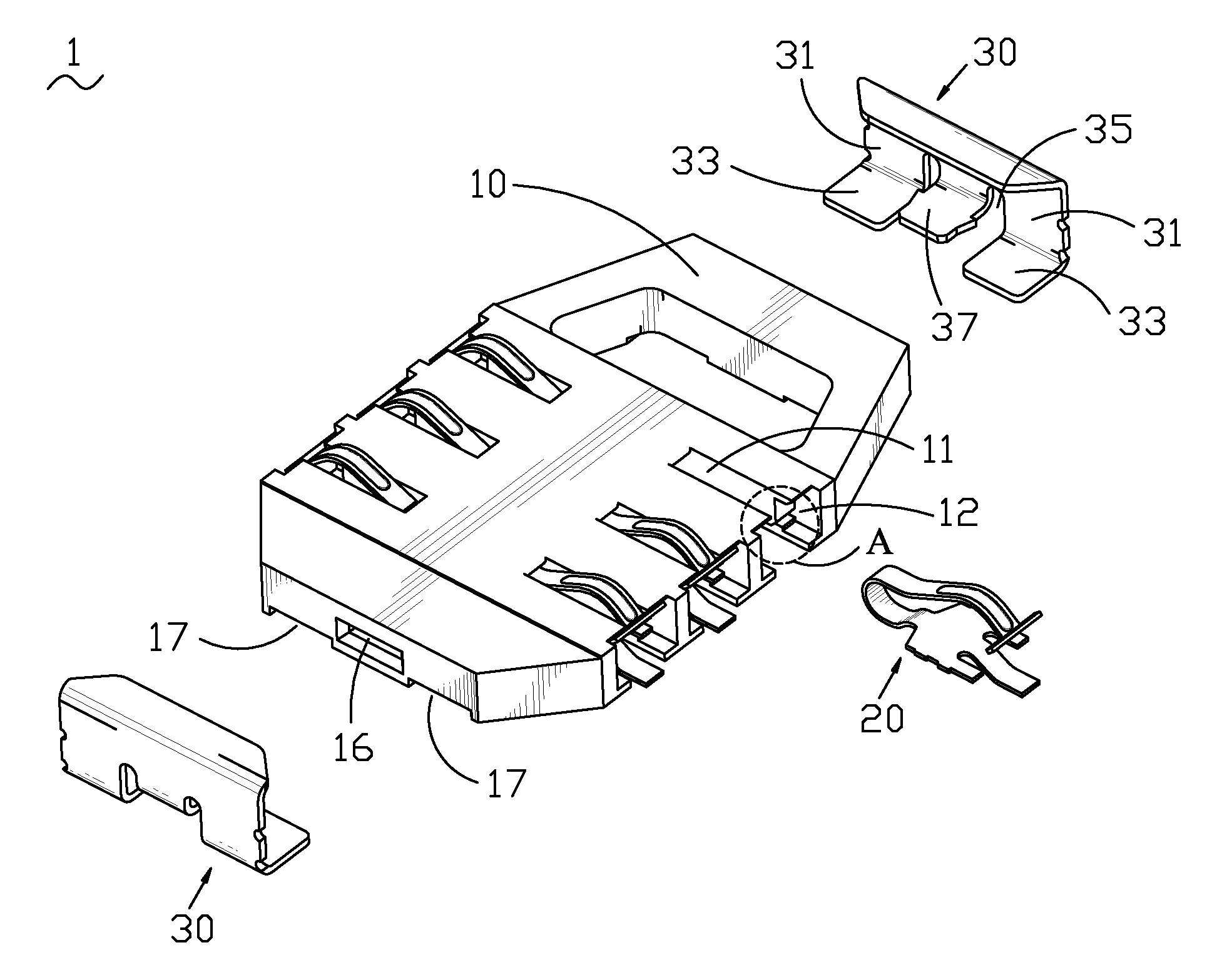
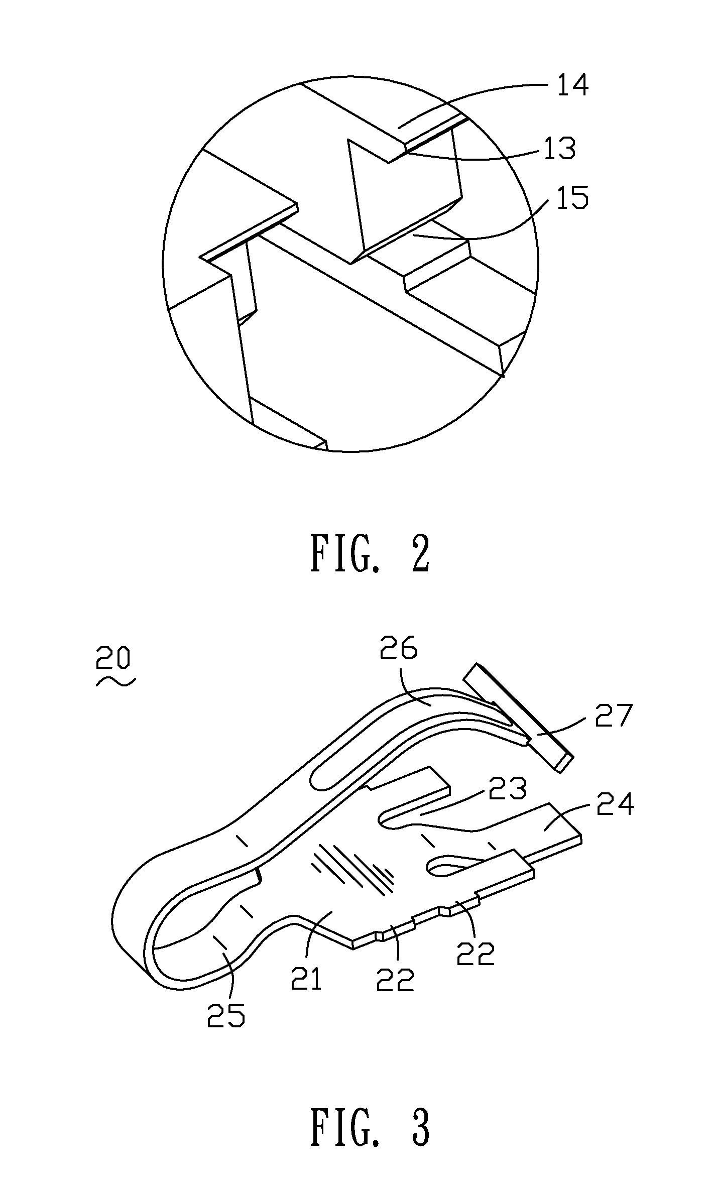
[0022]Referring to FIG. 1 to FIG. 3, a card connector 1 adapted for a Subscriber Identity Model (SIM) card according to a first embodiment of the present invention includes an insulating housing 10, a plurality of contacts 20 is disposed in a front portion and a rear portion of the insulating housing 10 respectively and two retaining members 30 are disposed in two opposite side ends of the insulating housing 10.

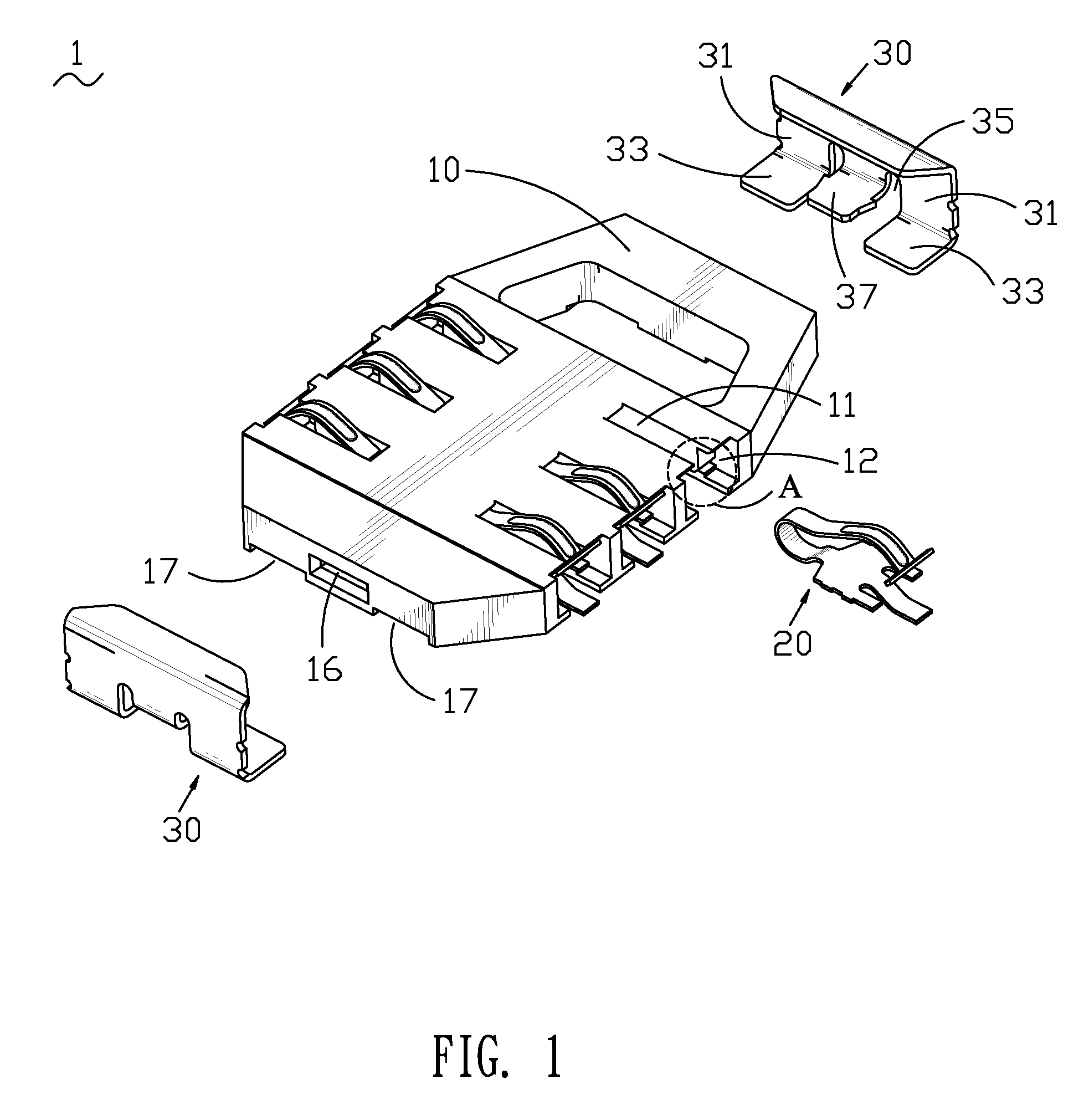
[0023]With reference to FIG. 1 and FIG. 2, the insulating housing 10 is of substantially a flat board-shape and defines a plurality of contact slots 11 divided into two groups. One group of the contact slots 11 is defined at the front portion of the insulating housing 10, while the other group of the contact slots 11 is arranged at the rear portion thereof. The insulating housing 10 further defines pairs of receiving recesses 15 at a bottom portion thereof. Each pair of the receiving recesses 15 is disposed at lateral sides of each corresponding contact slot 11 and communicat...


PUM


Abstract

A card connector is disclosed that includes an insulating housing and a plurality of contacts. The insulating housing defines a plurality of contact slots. Each of the contact slots extends outwardly and laterally to opposite sides to form two resisting protrusions respectively, wherein each of the resisting protrusions forms a resisting surface extending obliquely and inwardly from one side thereof. The contacts are respectively received in the contact slots of the insulating housing. Each of the contacts has a contact portion protruding upwardly for being pressed by a card and the contact portion is connected with a bearing portion resisting against the resisting surface for preventing the contact portion from flipping upwardly out of the insulating housing.

Description

BACKGROUND OF THE INVENTION[0001]1. Field of the Invention[0002]The present invention generally relates to a card connector, and more particularly to a card connector adapted for a Subscriber Identity Model (SIM) card.[0003]2. The Related Art[0004]Card connectors are broadly used in many electronic devices such as mobile phones, digital cameras and so on for transmitting data between the electronic devices and memory cards received in the electronic devices.[0005]Referring to FIG. 11, a conventional card connector is shown. The card connector includes an insulating housing 600 and a plurality of contacts 700 that are received in the insulating housing 600. The insulating housing 600 defines a plurality of contact slots 610 and pairs of halting gaps 620 all of which are divided into two groups with one group disposed in a front portion of the insulating housing 600 and the other group in a rear portion thereof. Each pair of the halting gaps 620 communicates with lateral sides of each...

Claims


Application Information

Patent Timeline
Patent Type & Authority Patents(United States)
IPC IPC(8): H01R24/00
CPCG06K7/0021H01R13/2442H01R12/7029
Inventor WANG, CHIN-CHOUHUANG, CHUNG-HSINYANG, MEI-CHUAN
Owner CHENG UEI PRECISION IND CO LTD
Why Eureka
Try Eureka