Molded fuel cell plates with seals

Inactive Publication Date: 2010-02-02
DANA AUTOMOTIVE SYST GRP LLC
View PDF23 Cites 8 Cited by
  • Summary
  • Abstract
  • Description
  • Claims
  • Application Information

AI Technical Summary

Benefits of technology

[0009]The invention offers two alternative methods for manufacturing sealed pairs of fuel cell plates in a simple and efficient manner. The first method employed involves the injection of a curable liquid silicone into an aligned mold aperture of one of the mated plates, whereby liquid silicone flows via the apertures through the other plate, as well as between the plates in order to establish a seal between the plates. Moreover, the liquid silicone is injected into aligned apertures of cathode and

Problems solved by technology

Further, grooves on mating surfaces of the plates include at least one projection, where

Method used


Image

  • Molded fuel cell plates with seals
  • Molded fuel cell plates with seals
  • Molded fuel cell plates with seals

Examples


Embodiment Construction

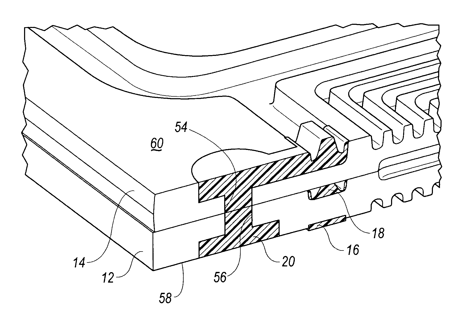
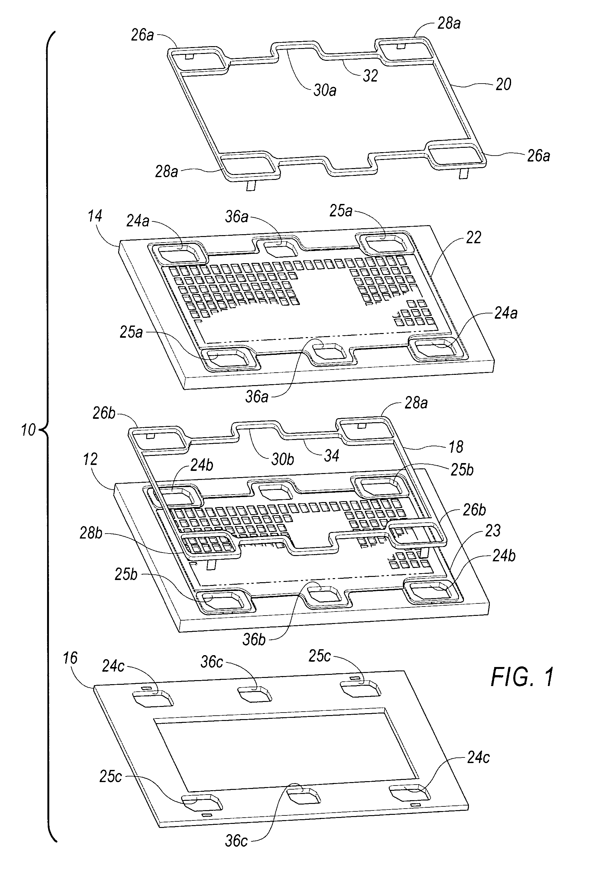
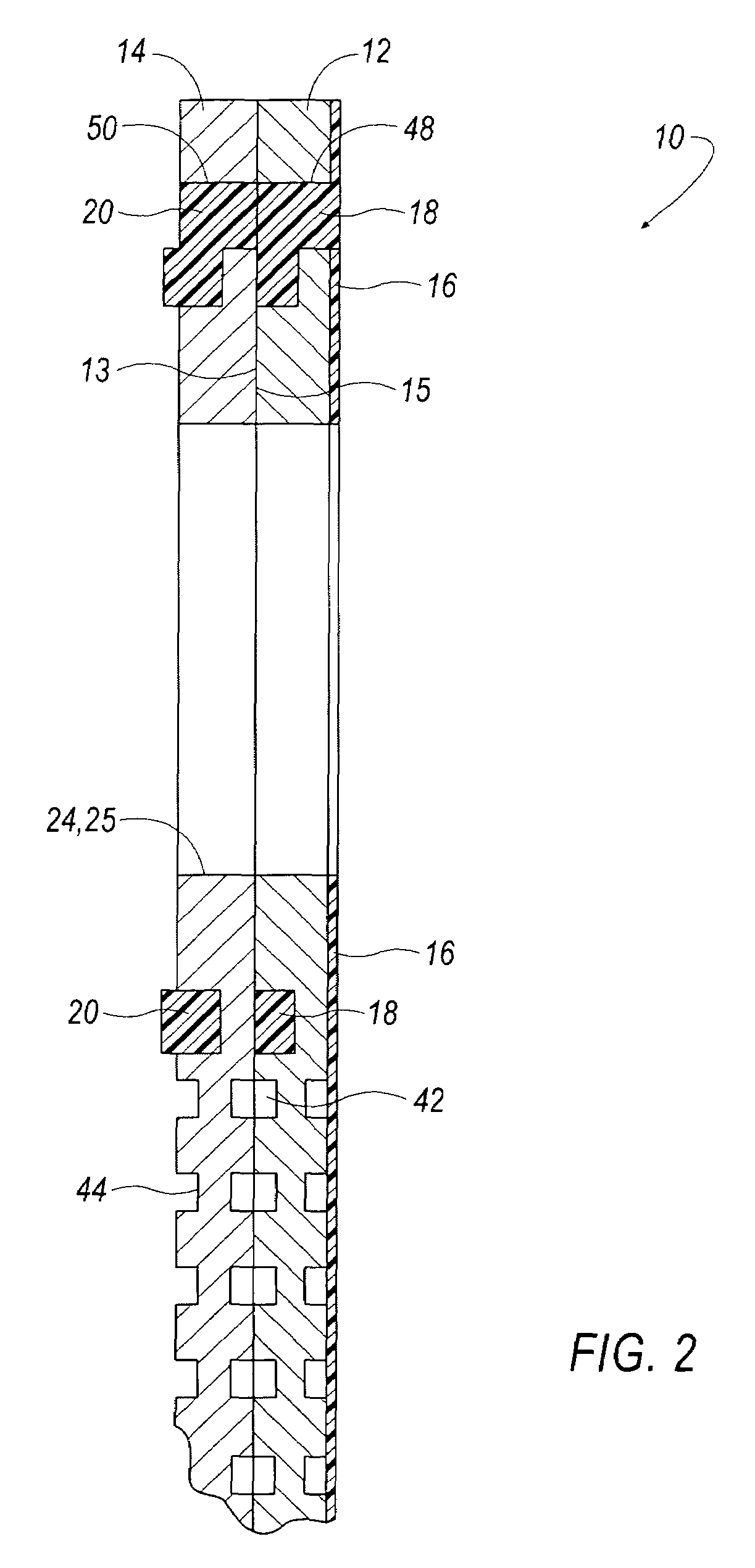
[0018]Referring to FIGS. 1 and 2, an electrolytic fuel cell unit 10 is shown, which includes an anode plate 12 and a cathode plate 14. Stacks of such fuel cell units 10 are assembled together to provide composite fuel cell structures (not shown) to generate electric power. In such a stack, an insulation layer 16 is interposed between each fuel cell unit 10.

[0019]First and second resilient media 18, 20, or gaskets, are interposed between each fuel cell unit 10, as well as between each plate 12, 14. Although the media 18, 20 are shown separately in FIG. 1, one embodiment of this invention provides a means by which the media 18, 20 are integrally connected in one single, contiguous mass of material as described below. In another embodiment of the invention, the insulation layer 16 is integrally formed with the first resilient media 18. The insulation layer 16 is preferably and generally thicker than the media 18, 20 in both embodiments.

[0020]Each of the media 18, 20 is accommodated by ...


PUM

PropertyMeasurementUnit
Pressureaaaaaaaaaa
Poweraaaaaaaaaa
Flow rateaaaaaaaaaa

Abstract

A fuel cell unit incorporates a pair of plates; one plate an anode, the other a cathode. Respective anode and cathode plates are physically bonded together to form such pairs; wherein pluralities of the pairs are secured together to form commercially available fuel cells utilized to generate electric power. Material employed between respective pairs of plates are in the nature of resilient media arranged about selected areas of the plates to confine paths for fluids adapted to flow within said selected areas. A method of manufacturing such fuel cell units involves the injection of a rapidly curable liquid silicone material into aligned apertures of the respective plates, whereby liquid silicone material flows through and between the plates to a) seal between respective anode and cathode plates and to b) form an insulation layer on the backside of the anode.

Description

CROSS REFERENCE TO RELATED APPLICATION[0001]This application is a continuation-in-part of application Ser. No. 10 / 456,228, filed Jun. 6, 2003 which is a continuation of application Ser. No. 09 / 858,165, filed May 15, 2001, now U.S. Pat. No. 6,599,653, the entire contents of which are herein incorporated by reference in its entirety.FIELD OF INVENTION[0002]The present invention relates to improved fuel cell assemblies for generating electric power, and more particularly to a method for providing resilient media between individual fuel cell plates and an insulation layer between fuel cell units.BACKGROUND OF THE INVENTION[0003]It is known to apply resilient sealing beads to and between the faces of fuel cell plates for controlling fluid flows between pluralities of such plates, stacked in pairs and bolted together for generating electric power. In a typical fuel cell stack arrangement, the pluralities of such plates are sandwiched together in a parallel, face-to-face pattern. The plate...

Claims


Application Information

Patent Timeline
IPC IPC(8): H01M2/08H01M2/00H01M2/14
CPCH01M8/0247H01M8/0271H01M8/0284Y10T29/49108Y02E60/50Y10T29/4911Y02P70/50
Inventor KUMMEROW, JACK A. C.DARKE, JOE B.ALSIP, DAVID C.
Owner DANA AUTOMOTIVE SYST GRP LLC
Why Eureka
Try Eureka