AI technical title is built by PatSnap AI team. It summarizes the technical point description of the patent document.
a technology of image sensing and vehicle headlights, applied in the direction of process and machine control, distance measurement, instruments, etc., can solve the problems of ineffective approaches, inability to reliably detect the taillights of leading vehicles, and inability to detect both
Inactive Publication Date: 2010-02-02
MAGNA ELECTRONICS INC
View PDF369 Cites 120 Cited by
Summary
Abstract
Description
Claims
Application Information
AI Technical Summary
This helps you quickly interpret patents by identifying the three key elements:
Problems solved by technology
Method used
Benefits of technology
Benefits of technology
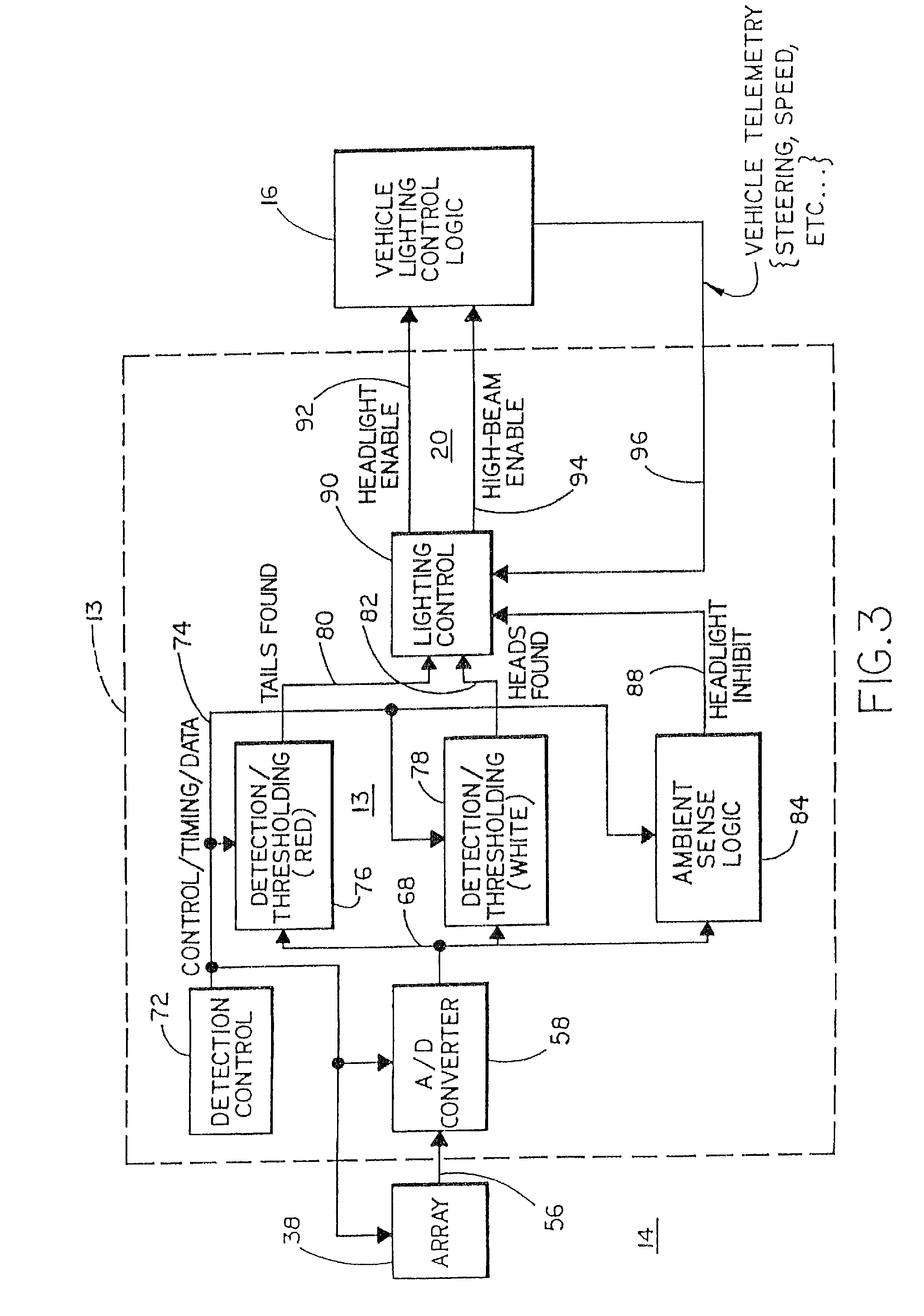
[0005]The present invention provides a vehicle control which is capable of identifying unique characteristics of light sources based upon a precise evaluation of light source characteristics made in each portion of the scene forward of the vehicle, in the vicinity of each light source, by separating each light source from the remainder of the scene and analyzing that source to determine its characteristics. One characteristic used in identifying a light source is the spectral characteristics of that source which is compared with spectral signatures of known light sources, such as those of headlights and taillights. Another characteristic used in identifying a light source is the spatial layout of the light source. By providing the ability to identify the headlights of oncoming vehicles and the taillights of leading vehicles, the state of the headlights of the controlled vehicle may be adjusted in response to the presence or absence of either of these light sources or the intensity of these light sources.
[0006]This is accomplished according to an aspect of the invention by providing an imaging sensor which divides the scene forward of the vehicle into a plurality of spatially separated sensing regions. A control circuit is provided that is responsive to the photosensors in order to determine if individual regions include light levels having a particular intensity. The control circuit thereby identifies particular light sources and provides a control output to the vehicle that is a function of the light source identified. The control output may control the dimmed state of the vehicle's headlamps.
[0007]In order to more robustly respond to the different characteristics of headlights and taillights, a different exposure period is provided for the array in order to detect each light source. In particular, the exposure period may be longer for detecting leading taillights and significantly shorter for detecting oncoming headlights.
Problems solved by technology
Such approaches have been ineffective.
Such prior art vehicle headlight dimming controls have also been ineffective at reliably detecting the taillights of leading vehicles.
The apparent reason is that the characteristics of these two light sources; for example, intensity, are so different that detecting both has been impractical.
While such modifications may have improved performance somewhat, the long-felt need for a commercially useful vehicle headlight dimming control has gone unmet.
Method used
Image
Click on the blue label to locate the original text in one second.
Reading with bidirectional positioning of images and text.
Examples
Embodiment Construction
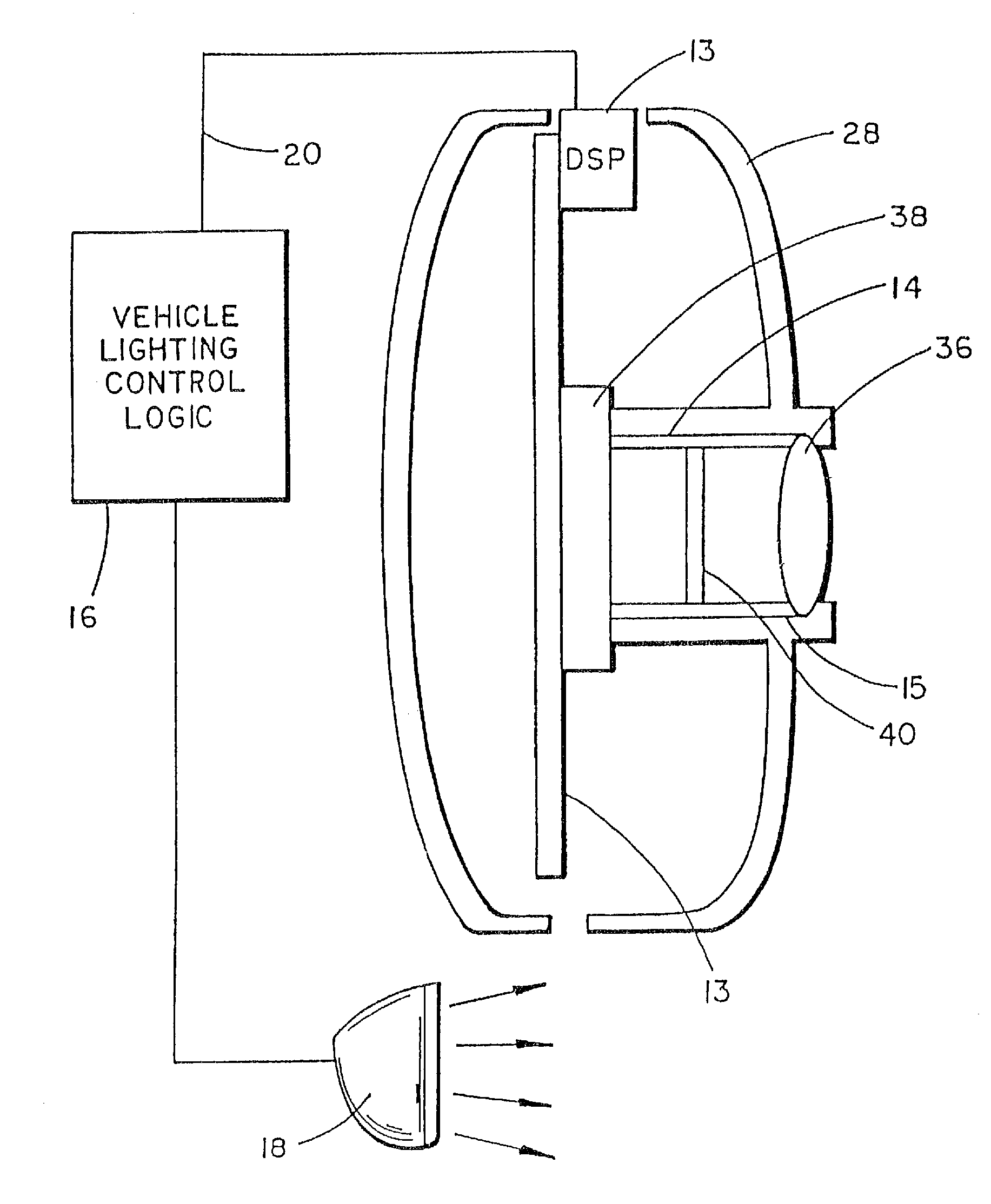
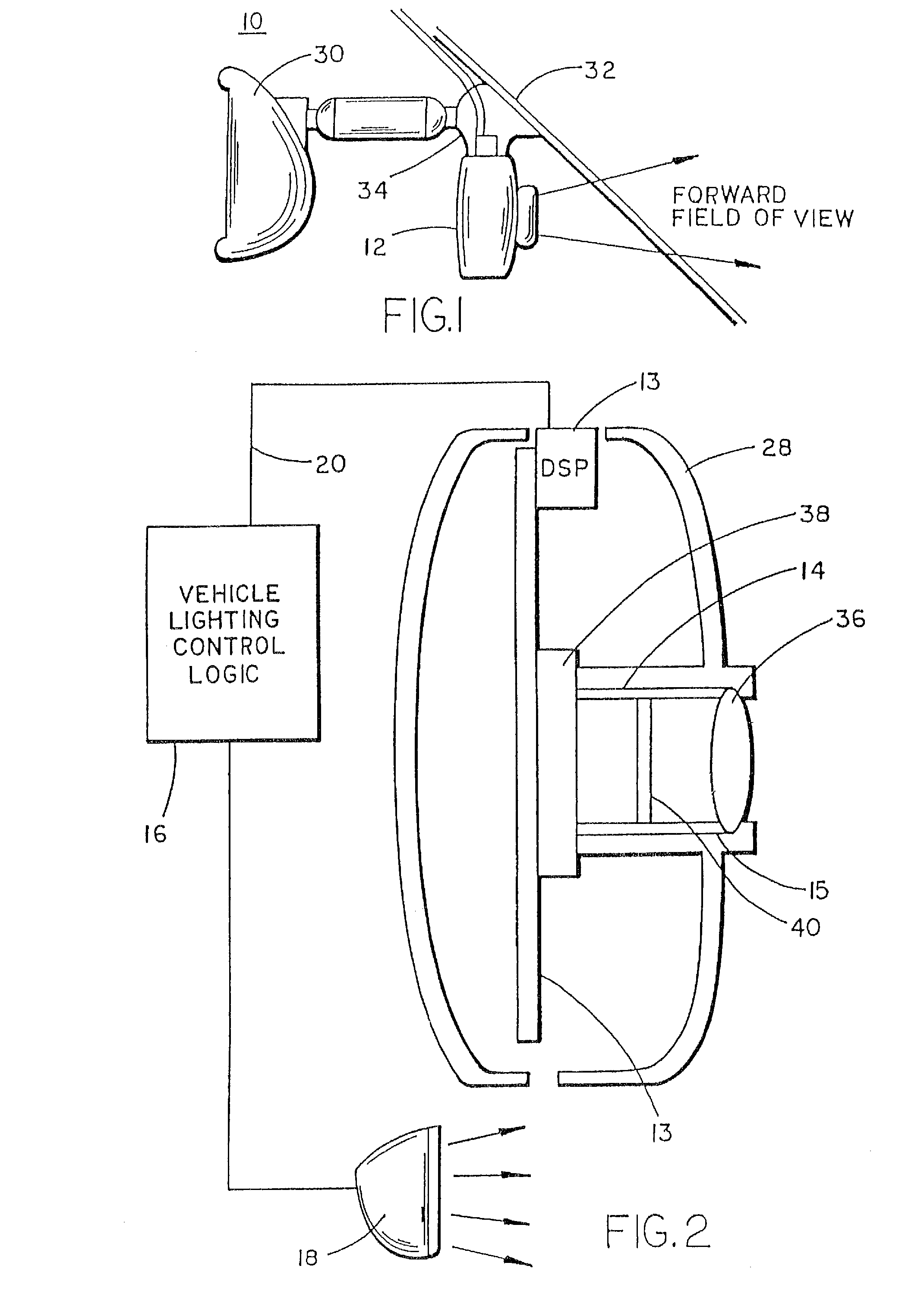
[0024]Referring now specifically to the drawings and the illustrative embodiments depicted therein, a vehicle 10 includes a vehicle headlight dimming control 12 made up of an imaging sensor module 14 which senses light from a scene forward of vehicle 10, an imaging control circuit 13 which receives data from sensor 14, and a vehicle lighting control logic module 16 which exchanges data with control circuit 13 and controls headlamps 18 for the purpose of modifying the headlight beam (FIGS. 1 and 2). Such control may be a binary control of the aim of the beam, such as by switching between lamps or lamp filaments, or may be a continuous variation of the aim of a single lamp more or less forward of the vehicle. The control may also control the intensity or pattern of the beam. Additionally, the lights of a vehicle equipped with daytime running lights may be switched between a daytime running light condition and a low-beam condition. Vehicle headlight dimming control 12 can perform a wid...
PUM
Abstract
An image sensing system for a vehicle includes an imaging sensor comprising a two-dimensional array of light sensing photosensor elements formed on a semiconductor substrate. The imaging sensor is disposed at an interior portion of the vehicle, and may be at or proximate to an interior rearview mirror assembly of the vehicle. The system includes a logic and control circuit comprising an image processor for processing image data derived from the imaging sensor. The image sensing system may identify objects of interest based on spectral differentiation or by comparing over successive frames image data associated with objects in the forward field of view of the image sensor or by objects of interest being at least one of qualified and disqualified based at least in part on object motion in the field of view of the imaging sensor.
Description
CROSS-REFERENCE TO RELATED APPLICATIONS[0001]This application is a continuation of U.S. patent application Ser. No. 11 / 626,535, filed Jan. 24, 2007, now U.S. Pat. No. 7,459,664, which is a continuation of U.S. patent application Ser. No. 11 / 545,039, filed Oct. 6, 2006, now U.S. Pat. No. 7,402,786, which is a continuation of U.S. patent application Ser. No. 09 / 441,341, filed Nov. 16, 1999, now U.S. Pat. No. 7,339,149, which is a continuation of U.S. patent application Ser. No. 09 / 135,565, filed Aug. 17, 1998, now U.S. Pat. No. 6,097,023, which is a continuation of U.S. patent application Ser. No. 08 / 621,863, filed Mar. 25, 1996, now U.S. Pat. No. 5,796,094.BACKGROUND OF THE INVENTION[0002]This invention relates generally to vehicle control systems and, in particular, to a system and method for controlling the headlights of the vehicles. The invention is particularly adapted to controlling the vehicle's headlamps in response to sensing the headlights of oncoming vehicles and taillight...
Claims
Application Information
Patent Timeline
Application Date:The date an application was filed.
Publication Date:The date a patent or application was officially published.
First Publication Date:The earliest publication date of a patent with the same application number.
Issue Date:Publication date of the patent grant document.
PCT Entry Date:The Entry date of PCT National Phase.
Estimated Expiry Date:The statutory expiry date of a patent right according to the Patent Law, and it is the longest term of protection that the patent right can achieve without the termination of the patent right due to other reasons(Term extension factor has been taken into account ).
Invalid Date:Actual expiry date is based on effective date or publication date of legal transaction data of invalid patent.

