Asynchronous change capture for data warehousing

a technology of data warehousing and asynchronous change, applied in the field of database systems, can solve the problems of cumbersome loading mechanism, cumbersome data acquisition and analysis, and computational cost, and achieve the effects of reducing the performance of the oltp system, reducing and increasing the cost of data acquisition

Inactive Publication Date: 2010-02-02
ORACLE INT CORP
View PDF19 Cites 31 Cited by
  • Summary
  • Abstract
  • Description
  • Claims
  • Application Information

AI Technical Summary

Problems solved by technology

Aggregating and analyzing this data, however, is computationally expensive and, if performed on the OLTP system itself, would decrease the performance of the OLTP system.
Conventional data extraction, transport, and loading mechanisms are cumbersome.
In this approach, the amount of data extracted, transported, and loaded is as immense as the amount of data in the OLTP system, even though only a small percentage of the data on the OLTP system is actually new.
Not only is this schema change an administrative nightmare, but many vendors of OLTP systems forbid their customers from making any change to the schema for security, maintenance, and liability reasons.
Second, there is a performance penalty in storing the timestamp for every row of new or changed data, yet performance is critical for OLTP systems.
Third, while timestamps can easily identify which rows have changed due to an insert or update, timestamps cannot distinguish between a newly inserted row or an old row that was updated.
Furthermore, timestamps cannot identify deleted rows, because deleted rows are no longer present in the database.
The lack of this kind of change information makes it difficult to properly update summaries of the OLTP data, resulting in expensive recalculations of the summary data.
Trigger-based change data capture has two disadvantages for many data warehousing deployments.
The first disadvantage is performance.
Because triggers are fired every time a row is updated, inserted, or deleted on the OLTP system, triggers impose a performance penalty on every operation performed on the OLTP system.
The overhead for trigger processing can be substantial, requiring as much as three times the amount of computing resources to process the same number of operations without triggers.
The second disadvantage is that the creation of a trigger is still technically a schema change and therefore forbidden by many turn-key OLTP systems.

Method used


Image

  • Asynchronous change capture for data warehousing
  • Asynchronous change capture for data warehousing
  • Asynchronous change capture for data warehousing

Examples


Embodiment Construction

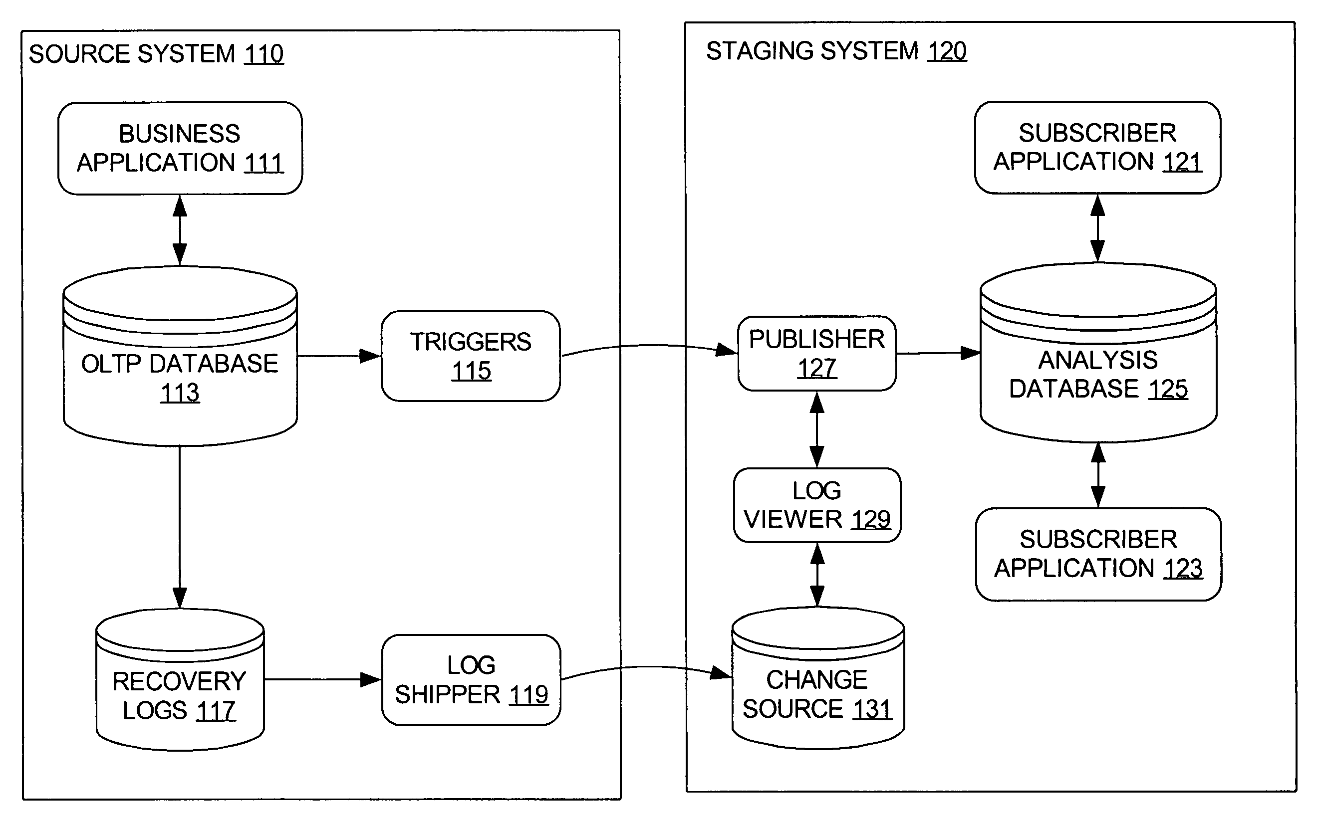
[0021]A system, method, and software for change data capture are described. In the following description, for the purposes of explanation, numerous specific details are set forth in order to provide a thorough understanding of the present invention. It is apparent, however, to one skilled in the art that the present invention may be practiced without these specific details or with an equivalent arrangement. In other instances, well-known structures and devices are shown in block diagram form in order to avoid unnecessarily obscuring the present invention.

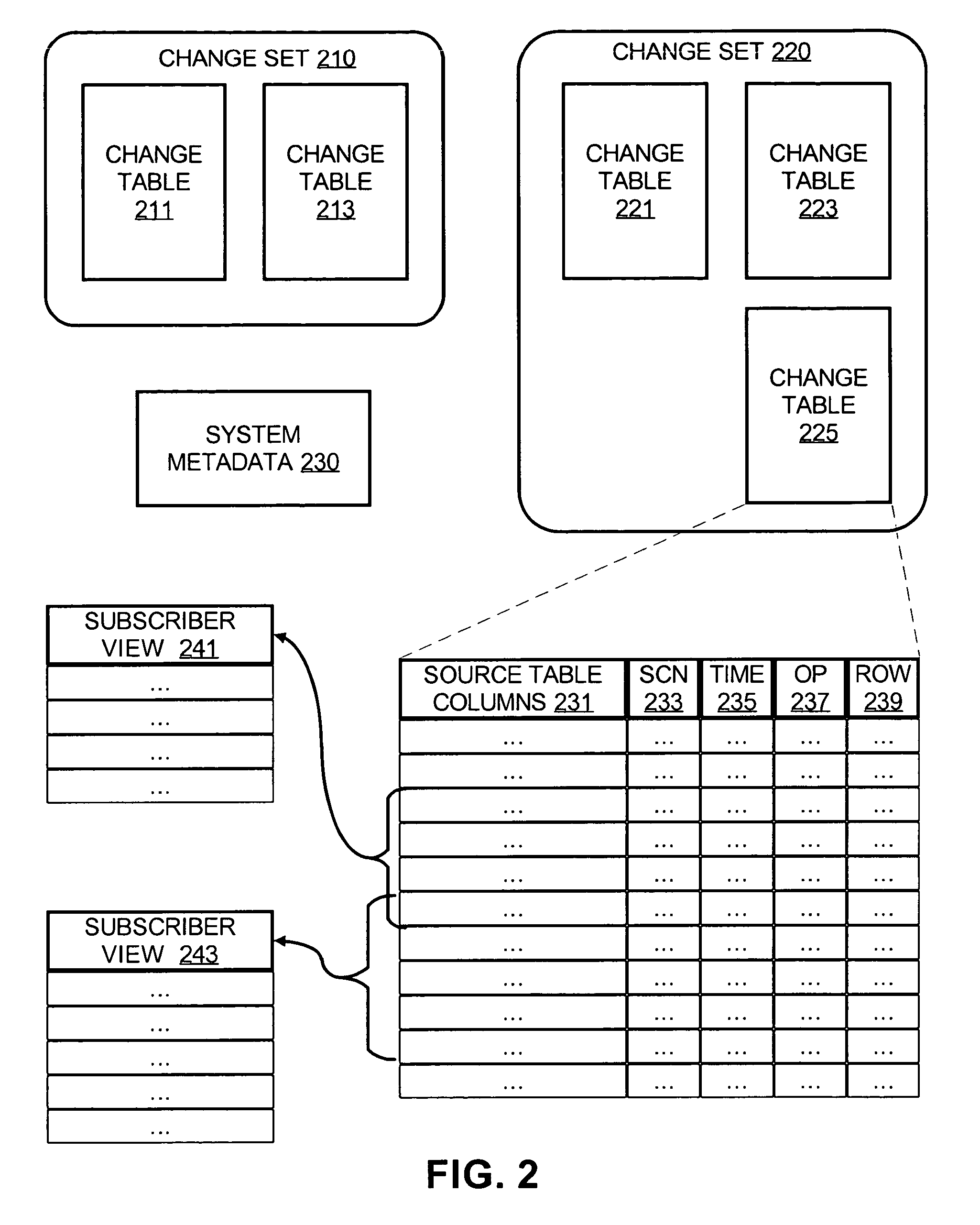
[0022]In a database management system, data is stored in one or more data containers, each container contains records, and the data within each record is organized into one or more fields. In relational database systems, the data containers are referred to as tables, the records are referred to as rows, and the fields are referred to as columns. In object-oriented databases, the data containers are referred to as object classes, the...


PUM


Abstract

A method and software for change data capture are disclosed, in which change data is extracted from a recovery log and stored in a database object. The change data indicates what modification has been performed to a source object on the OLTP system. In some embodiments of the present invention, a database statement may be generated and executed to extract and load the change data, and the recovery log itself may be shipped from an OLTP system to a staging system.

Description

RELATED APPLICATIONS[0001]The present application is related to U.S. patent application Ser. No. 10 / 140,818 entitled “Method and Apparatus for Change Data Capture in a Database System” filed on May 9, 2002 by William D. Norcott et al.[0002]The present application is related to U.S. patent application Ser. No. 09 / 863,422 entitled “Synchronous Change Data Capture in a Relational Database” filed on May 24, 2001 by William D. Norcott, the contents of which are hereby incorporated by reference.FIELD OF THE INVENTION[0003]The present invention relates to database systems and more particularly to asynchronous change capture for data warehousing.BACKGROUND OF THE INVENTION[0004]Many businesses and other large organizations today use relational database management systems known as on-line transaction processing (OLTP) systems to execute and keep track of business transactions. For example, a company that sells products or services over the Internet may use an OLTP system to record pricing in...

Claims


Application Information

Patent Timeline
Patent Type & Authority Patents(United States)
IPC IPC(8): G06F12/00G06F17/30
CPCG06F17/30563G06F16/254Y10S707/99953
Inventor NORCOTT, WILLIAM D.
Owner ORACLE INT CORP
Why Eureka
Try Eureka