
Image-processing apparatus, an image-forming apparatus, and a program

a technology of image processing and image, applied in the field of image processing apparatus, image forming apparatus, and program, can solve the problems of error-diffusion process, inability to address a problem, and image quality degradation, so as to reduce the amount of memory use and reduce the degradation of the image quality of the processed imag

Inactive Publication Date: 2010-02-09
RICOH KK
View PDF24 Cites 12 Cited by
  • Summary
  • Abstract
  • Description
  • Claims
  • Application Information

AI Technical Summary

Benefits of technology

[0017]In light of the problems as described above, it is a general object of the present invention to provide an image-processing apparatus, an image-forming apparatus, and a program that prevent a stripe-shaped pseudo-contour, produced at a border where error-diffused processing units adjoin, from standing out, so as to reduce degradation in the image quality of the processed image, making it possible to divide the processing units into multiple small areas so as to thereby enable a reduction in the amount of memory use.

Problems solved by technology

Moreover, in the multi-level error-diffusion process, there is also a problem of decreased image quality due to a delay in dot generation in a portion such that an N-level quantization output changes.
However, while what is described in the Patent Document 1 solves a problem of an image distortion due to a delay in dot generation, it focuses attention on a single image or on an output result in a single error-diffusion process.
Therefore, it does not address a problem of a pseudo-contour (a portion indicated with R in FIG. 11) being produced when adjoining and combining multiple error-diffused images or when dividing a single image into multiple areas so as to error-diffuse each of the areas.
Thus, there is a problem in that a pseudo-contour may be produced such as a portion indicated with R in FIG. 13 due to dots being generated too soon when the images are adjoined even when a delay in dot generation is improved such as a portion indicated with R in FIG. 12.
However, adjoining and combining such images together as described above causes a tendency of border portions to stand out and causes visual discomfort even with a small discontinuity, especially when both of the border portions are of the same tone.
In such a case, it is likely that the same tone will continue in the process border so that a delay or a lead in dot generation is prone to becoming a problem.
There is a problem that in such a border at which the error-diffused image units adjoin, a stripe shape such that there is an empty gap (a portion indicated with R in FIG. 11) appears when there is a delay in dot generation while a dense stripe shape (a portion indicated with R in FIG. 13) appears when there is a lead in dot generation.

Method used


Image

  • Image-processing apparatus, an image-forming apparatus, and a program
  • Image-processing apparatus, an image-forming apparatus, and a program
  • Image-processing apparatus, an image-forming apparatus, and a program

Examples


Embodiment Construction

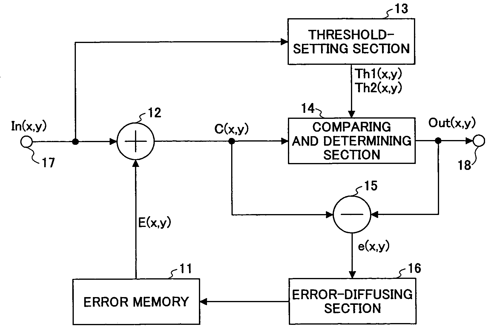
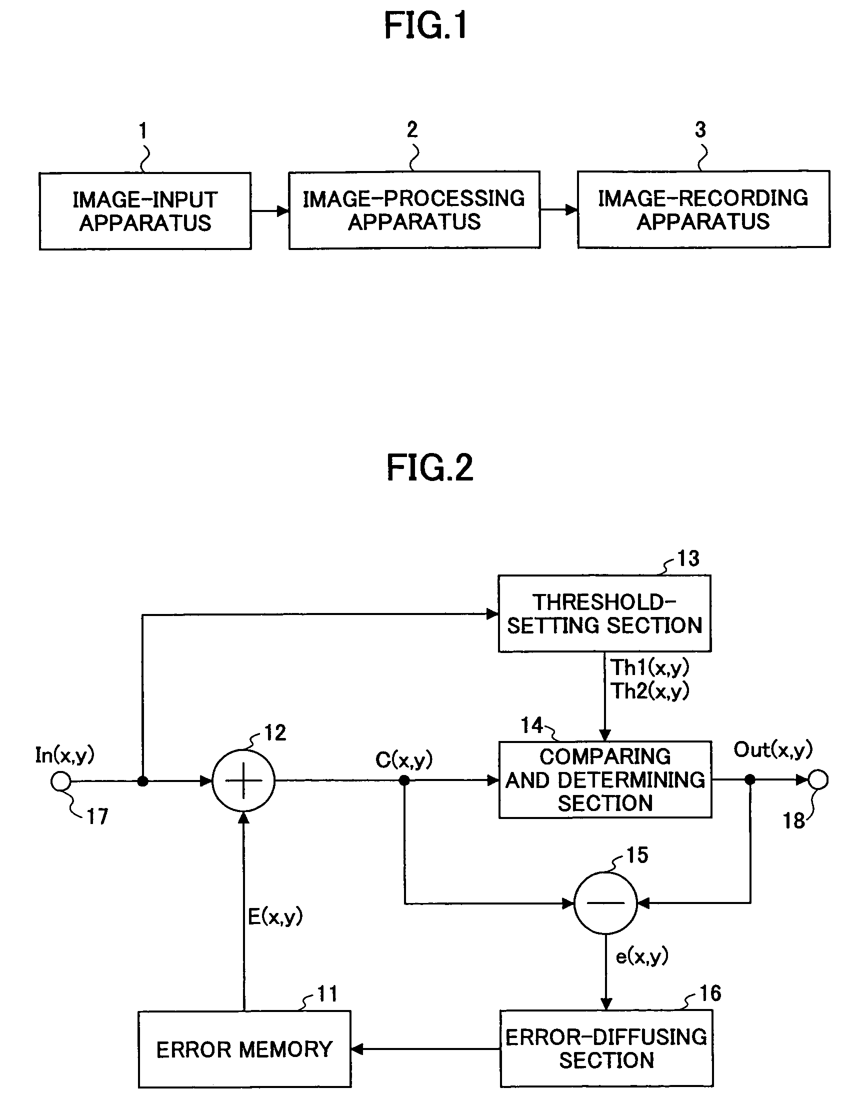
[0036]In the following, embodiments of the present invention are described with reference to the accompanying drawings. First, an image input / output system comprising an image-processing apparatus pertaining to the present invention is described with reference to FIG. 1.

[0037]This image input / output system comprises: an image-input apparatus 1 which is an input device such as a scanner or a digital camera; an image-processing apparatus 2 configured with a personal computer, etc., which includes processing means for quantizing multi-level (M-level) image data into N values (where M>N>1) using a multi-level error-diffusion process or a multi-level minimum average error method for taking in input-image (eg., 256-tone image for 8-bit accuracy) data from the image-input apparatus 1 and performing on this 256-tone image data necessary processes such as converting to a number of tones which it is possible to output at a later-stage image-output apparatus 3 so as to output as image data; an...


PUM


Abstract

An image-processing apparatus for quantizing multi-level (M-level) image data into N-level values, where M>N>1, using a multi-level error-diffusion process or a minimum-average multi-level error method is disclosed.The image-processing apparatus includes: means for outputting correction data; means for setting a quantization-threshold value; means for comparing the correction data and the quantization-threshold value so as to output N-level image data; and means for calculating an error generated with generating the N-level image data.

Description

TECHNICAL FIELD[0001]The present invention generally relates to an image-processing apparatus, an image-forming apparatus, and a program.BACKGROUND ART[0002]A pseudo-intermediate tone process is known as a method of converting, in an image input / output system for outputting to an output apparatus such as a printer or a display multi-value image data read with an input apparatus such as a scanner or a digital camera, the multi-level (eg. 256 tones for an 8-bit accuracy) image data read with the input apparatus into image data having a number of tones which the output apparatus can output and pseudo-representing successive tones.[0003]As this pseudo-intermediate tone process, a bi-level process is conventionally performed when the output apparatus can only represent a bi-level of ON / OFF of a dot. As this bi-level process, there are an error-diffusion process and a minimum-average error method that produce superior resolution and tone. The error-diffusion and minimum-average error meth...

Claims


Application Information

Patent Timeline
Patent Type & Authority Patents(United States)
IPC IPC(8): H04N1/40G06K15/00H04N1/405
CPCH04N1/40087
Inventor IKE, TAKAHIROHIRANO, MASANORI
Owner RICOH KK
Learn More