

Optical lens system for taking image
a technology of optical lens and image, applied in the field of optical lens system for taking image, can solve the problems of difficult control of the gluing process of glass lens elements, difficulty in reducing the length of the whole optical system, and the degree of freedom of the optical system, so as to improve the image quality of the optical system and effectively reduce the size of the optical lens system
- Summary
- Abstract
- Description
- Claims
- Application Information
AI Technical Summary
Benefits of technology
Problems solved by technology
Method used
Image

Examples
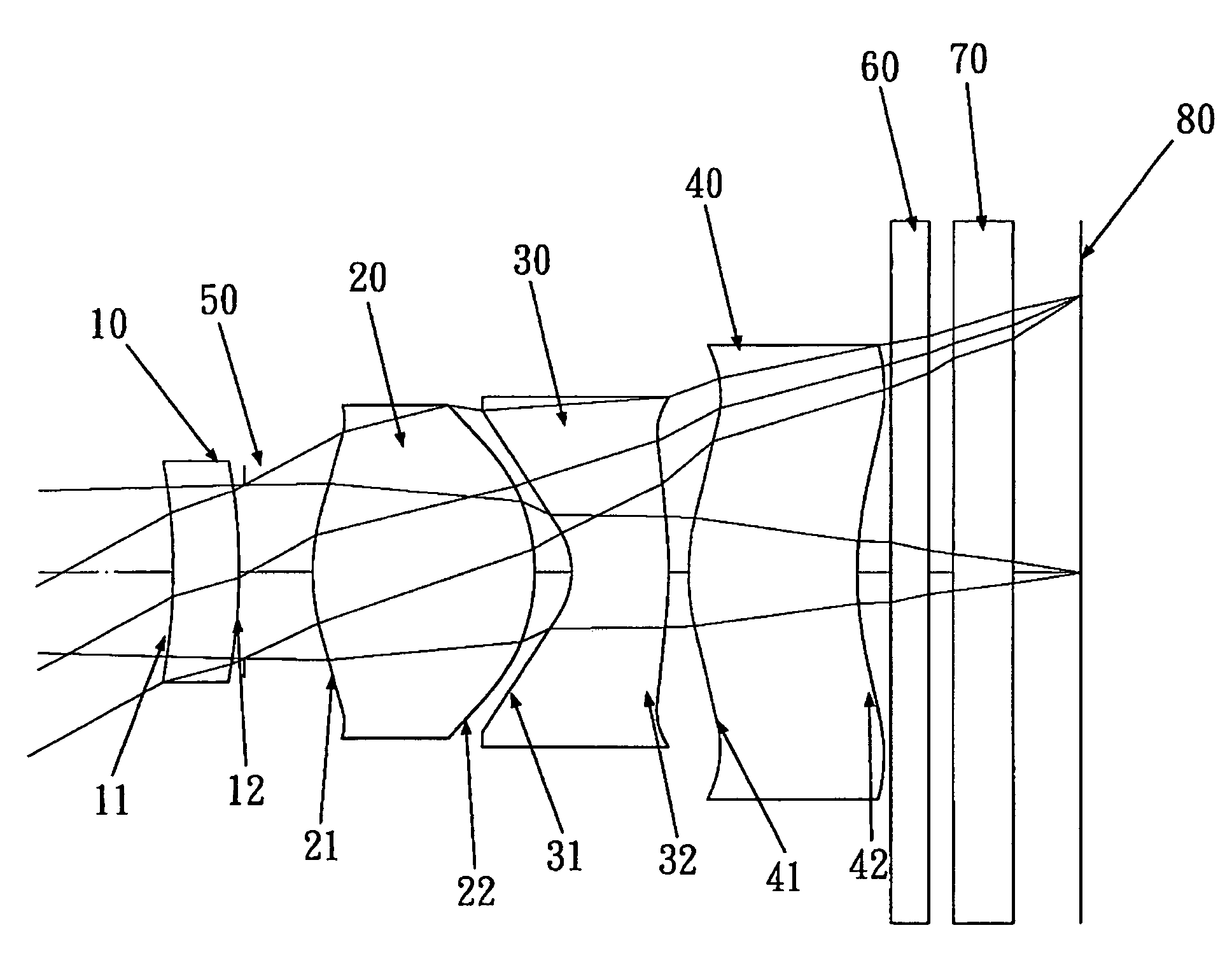
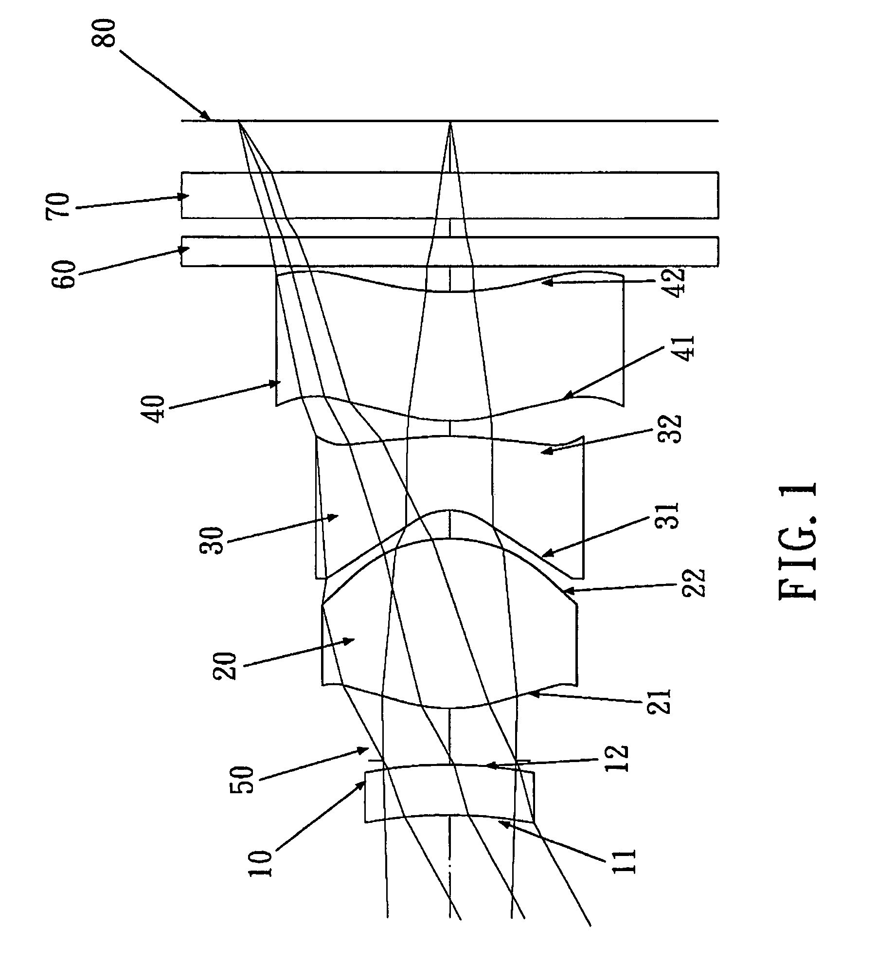
first embodiment
[0061]In the present optical lens system for taking image, the Abbe number of the first lens element is V1, the Abbe number of the third lens element is V3, and they satisfy the relations:
V3=30.2
|V1−V3|=25.6.
[0062]In the first embodiment of the present optical lens system for taking image, the focal length of the first lens element is f1, the focal length of the second lens element is f2, the focal length of the third lens element is f3, the focal length of the optical lens system for taking image is f, and they satisfy the relations:
f / f1=−0.21
f / f2=2.05
f / f3=−2.3.
[0063]In the first embodiment of the present optical lens system for taking image, the center thickness of the second lens element is CT2, the edge thickness of the second lens element is ET2, and they satisfy the relation:
CT2 / ET2=2.08.
[0064]The edge thickness is: the length projected on an optical axis by the distance between the positions of the effective diameter of the front and the rear surfaces of the lens.
[0065]In the...
second embodiment
[0079]In the present optical lens system for taking image, the Abbe number of the first lens element is V1, the Abbe number of the third lens element is V3, and they satisfy the relations:
V3=23.4
|V1−V3|=32.4.
[0080]In the second embodiment of the present optical lens system for talking image, the focal length of the first lens element is f1, the focal length of the second lens element is f2, the focal length of the third lens element is f3, the focal length of the optical lens system for taking image is f, and they satisfy the relations:
f / f1=−0.14
f / f2=1.77
f / f3=−1.68.
[0081]In the second embodiment of the present optical lens system for taking image, the center thickness of the second lens element is CT2, the edge thickness of the second lens element is ET2, and they satisfy the relation:
CT2 / ET2=2.21.
[0082]The definition of the edge thickness of the second embodiment is the same as that of the first embodiment.
[0083]In the second embodiment of the present optical lens system for taking...
third embodiment
[0097]In the present optical lens system for taking image, the Abbe number of the first lens element is V1, the Abbe number of the third lens element is V3, and they satisfy the relations:
V3=30.2
|V1−V3|=30.1.
[0098]In the third embodiment of the present optical lens system for taking image, the focal length of the first lens element is f1, the focal length of the second lens element is f2, the focal length of the third lens element is f3, the focal length of the optical lens system for taking image is f, and they satisfy the relations:
f / f1=−0.01
f / f2=2.10
f / f3=−2.22.
[0099]In the third embodiment of the present optical lens system for taking image, the center thickness of the second lens element is CT2, the edge thickness of the second lens element is ET2, and they satisfy the relation:
CT2 / ET2=2.13.
[0100]The definition of the edge thickness of the third embodiment is the same as that of the first embodiment.
[0101]In the third embodiment of the present optical lens system for taking imag...
PUM
 Abstract
Description
Claims
Application Information