Radiation imaging system

a technology of radiation imaging and imaging system, which is applied in the direction of nuclear radiation detection, instruments, measurement devices, etc., can solve the problems of inability to meet the requirements of data transmission amount on the original bus, disadvantageous expansion of the design of the dedicated data transmission bus, and inability to achieve high-speed data acquisition when a car is running very fast, etc., to achieve the effect of increasing the speed of data acquisition of the x-ray inspection system, broad adaptability, and reducing the number o

Inactive Publication Date: 2010-02-09
TSINGHUA UNIV +1
View PDF3 Cites 0 Cited by
  • Summary
  • Abstract
  • Description
  • Claims
  • Application Information

AI Technical Summary

Benefits of technology

[0007]An object of the present invention is to provide a high-speed radiation imaging system for performing inspections on rail vehicles, which allows high-speed stability to the collection of data and transform data, and correct and reliable transmission of data, when the inspected objects are passing through the scanning passage at high speeds. When the number of detecting units increases, it is possible to meet requirements through extending the data acquisition system.
[0018]According to the present invention, the speed of data acquisition of the X-ray inspection system is increased, since the extensibility thereof has broad adaptability, which may be not only adapted to the rail vehicles inspection system with such as 30 km / h or higher operating rate and greater data amount, abut also adapted to the other products in the nondestructive detection field.

Problems solved by technology

Particularly, how to achieve high-speed acquisition for data when a car is running very fast, such as at a speed of 30 km per hour, is a main confronted problem.
Considering the inspection system for high-speed acquisition, the design of a dedicated data transmission bus is disadvantageous for extending.
When the number of detecting units is increased, the amount of data transmission on the original bus can not meet requirements, and it is needed to redesign the system.
However, the field bus technology applied in the radiation inspection systems has a lower transmission rate, such as CAN bus, the highest transmission rate thereof is 1 Mbps, and can not satisfy the tasks for real-time high-speed acquisition and transmission of mass data.

Method used


Image

  • Radiation imaging system
  • Radiation imaging system
  • Radiation imaging system

Examples


Embodiment Construction

[0025]Hereafter preferred embodiments of the present invention will be explained in detail with reference to the drawings. In the drawings, the like reference numbers refer to the same or the like components in the different drawings. For the clarify and simplicity, the detail descriptions for the already known functions and structures herein will be omitted, in order to avoid obscuring the subject matter of the present invention.

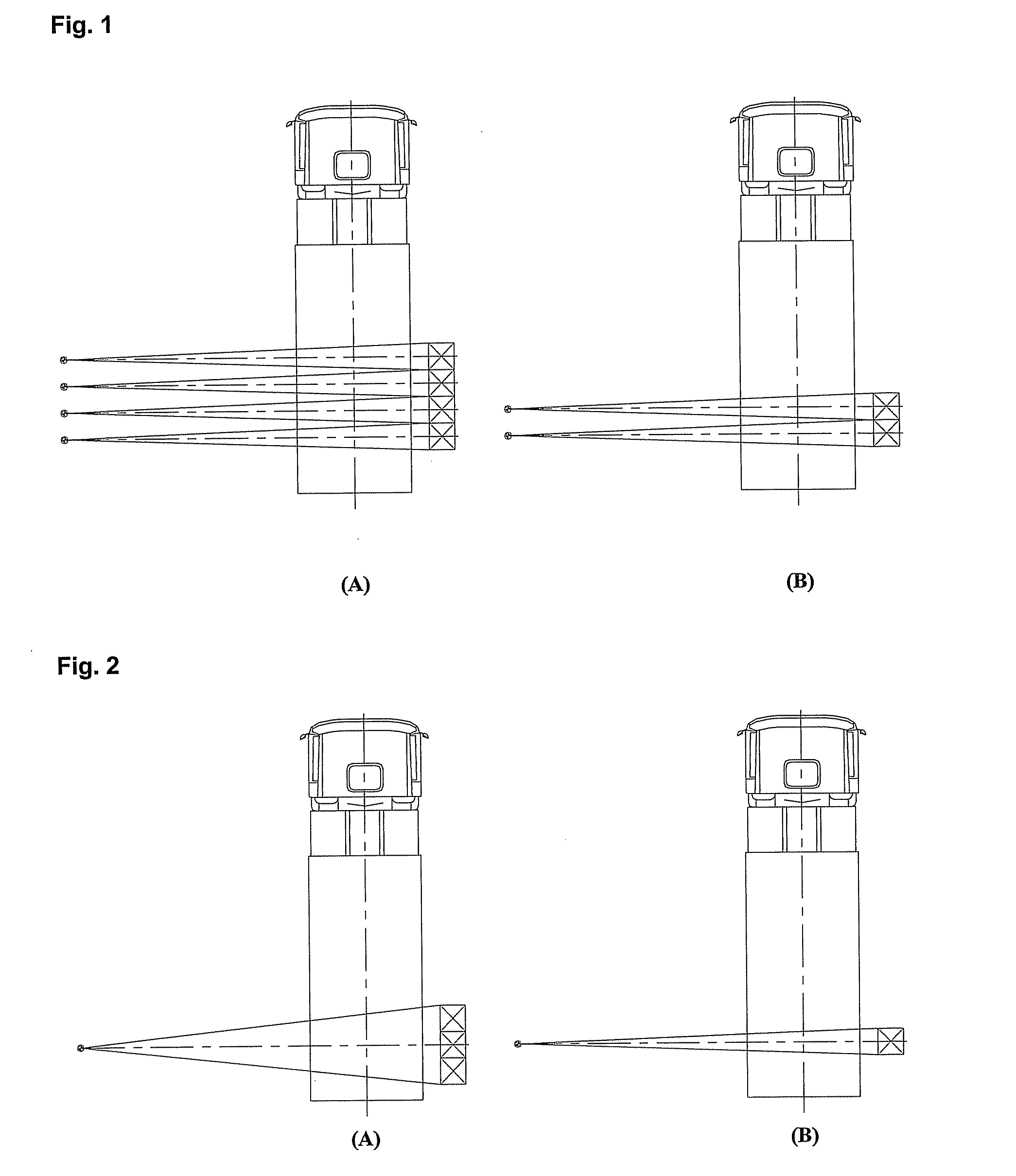
[0026]FIG. 1 is a schematic diagram for illustrating a rapid triggered scanning manner of the present invention and a slow triggered scanning manner of the prior art. As shown in (A) and (B) of FIG. 1, an accelerator generates X-rays with high frequency under control, the frequency thereof is Hundreds of Hertz per second, and It can product one column image in each pulse. Therefore, the more pulse rays there are in unit time, the more column images formed in unit time, thereby increasing the speed of the scanning imaging. That is, it is possible to increase...


PUM

PropertyMeasurementUnit
scanning frequencyaaaaaaaaaa
speedaaaaaaaaaa
scanning speedaaaaaaaaaa

Abstract

The present invention discloses an radiation imaging system, comprising: an accelerator for generating rays which penetrate through the objects to be inspected and an synchronous signal; a detector with a plurality of detecting modules, adapted for detecting rays; a signal processor for generating a selection signal according to the synchronous signal, so as to select a detecting module for detecting the rays; a data converter for converting the signal detected by said detecting module into digital data, and then buffering the digital data in said signal processor; and a communication controller connected to an image processor, adapted for transmitting the digital data buffered in said signal processor to said image processor. The system according to the present invention allows high-speed and stable data acquisition and data conversion and accurate and reliable data transmission, when the data amount is significant.

Description

FIELD OF THE INVENTION[0001]The present invention relates to a radiation imaging system, more specifically, to a radiation imaging system that can make radiation imaging for high speed cars and obtain clear images.BACKGROUND OF THE INVENTION[0002]The present application claims priority of Chinese patent application Serial No. 200710118200.7, filed Jul. 2, 2007, the content of which is hereby incorporated by reference in its entirety.[0003]During scan imaging, an accelerator generates high-energy X-ray pulses, which penetrate through the object under scan. Detector arrays with high sensitivity receive the X-rays, and convert them into an electrical signal for output. Then, columns of digital images are generated in real time by an image acquisition subsystem. When the entire scanning process completes, a whole image for the scanned object will be obtained at a system control station.[0004]In an imaging system, a main function of an accelerator is to generate X-ray pulses under contro...

Claims


Application Information

Patent Timeline
Patent Type & Authority Patents(United States)
IPC IPC(8): G01N23/04
CPCG01N23/04G01V5/0008
Inventor KANG, KEJUNCHEN, ZHIQIANGLI, YUANJINGWANG, LIMINGLIU, YINONGSUN, SHANGMINZHANG, LILIU, YAOHONGYANG, GUANGZHANG, QINGJUNLIU, WENGUOLIANG, SIYUANGUO, ZHENBINHU, BINDENG, YANLIWU, YUCHENG
Owner TSINGHUA UNIV
Why Eureka
Try Eureka