Ultrasound diagnosis apparatus

a technology of ultrasound diagnosis and ultrasound beam, which is applied in the field of ultrasound diagnosis apparatus, can solve the problems of difficulty in accurately acquiring volume data of quickly moving organs or blood flow, and the mechanical data acquisition type ultrasound diagnosis apparatus cannot accurately acquire volume data in a short time, so as to achieve uniform thin beam width, superior image quality, and large beam width

Active Publication Date: 2014-11-18
TOSHIBA MEDICAL SYST CORP
View PDF17 Cites 0 Cited by
  • Summary
  • Abstract
  • Description
  • Claims
  • Application Information

AI Technical Summary

Benefits of technology

[0017]The present invention solves the above-mentioned conventional problems and defects, and provides an ultrasound diagnosis apparatus that can acquire 3D ultrasound image volume data in a short time while avoiding deterioration of the transmission / reception sensitivity and the sensitivity unevenness. According to the ultrasound diagnosis apparatus consistent with the present invention, the number of the parallel simultaneous reception beams can be increased to more than 5 in order to increase a volume data acquisition speed (volume rate). Further, it is possible to avoid the sensitivity unevenness among the parallel simultaneous reception beams and to improve the S / N ratio for the volume data.
[0032]The ultrasound diagnosis apparatus according to embodiments of the present invention performs ultrasound parallel simultaneous reception by a transmitting acoustic field having a relative larger beam width and a plurality of reception beams, each having a uniform thin beam width, that are spaced apart a prescribed angular distance Δξ from a center axis of the transmitting acoustic field. The ultrasound diagnosis apparatus according to the present invention further performs 3D scans on a 3D region of an object by sequentially shifting a transmission / reception group that is comprised of each of the transmitting acoustic fields and more than five (5) parallel simultaneous reception beams corresponded to each of the transmitting acoustic field, at a prescribed of angular distance Δξ0 along the θ (azimuth) direction and the φ (elevation) direction. According to the ultrasound diagnosis apparatus consistent with the present invention, it becomes possible to generate and display a 3D ultrasound image data of superior image quality in real time.

Problems solved by technology

While a mechanical data acquisition type ultrasound diagnosis apparatus is relatively easy to construct, it needs a lot of time for acquiring volume data.
Accordingly, it is very difficult for the mechanical data acquisition type ultrasound diagnosis apparatus to correctly acquire data of quickly moving organs or blood flow.
On the contrary, although an ultrasound probe and a main body for an electrically data acquisition type ultrasound diagnosis apparatus requires complex constructions, it can acquire volume data in a short time.
However, while the triggered volume scan is effective to the diagnosis for a circulation organ, it can not to apply to an object having a severe arrhythmia.
Further, since a blood flow measurement under the ultrasound Doppler method requires a plurality of ultrasound transmissions and receptions on the same portion in order to acquire the flood speed data, it becomes difficult to display 3D color Doppler image data in real time.
However, when the number of the receiving beams for the parallel simultaneous reception is increased to more than five (5) in order to increase an acquisition rate of the volume data (volume rate), it becomes impossible to obtain equal transmission / reception sensitivity by applying the conventional parallel simultaneous reception method.
Thus, problems of sensitivity unevenness and sensitivity differences would occur.
This causes a non-permissible problem of sensitivity unevenness in the acquired volume data.
Consequently, the transmission / reception sensitivities for each of the reception beams are deteriorated.
This causes another problem of a deterioration of the S / N ratio for the volume data.

Method used


Image

  • Ultrasound diagnosis apparatus
  • Ultrasound diagnosis apparatus
  • Ultrasound diagnosis apparatus

Examples


Embodiment Construction

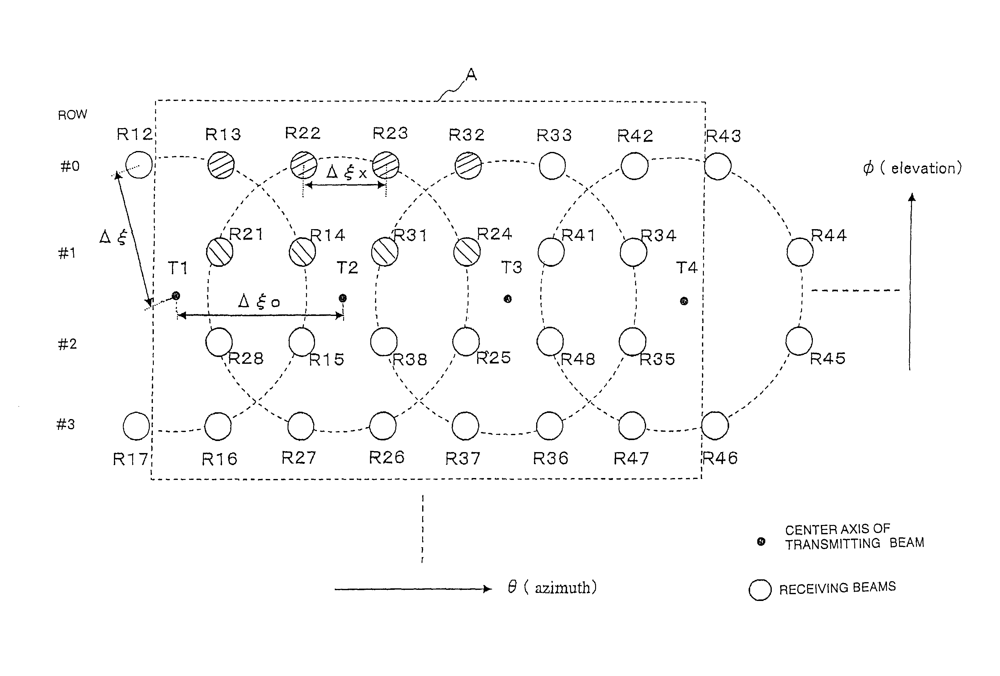
[0050]According to embodiments of the present invention, 3D ultrasound volume data of an even transmission / reception sensitivity to a 3D region in an object can be acquired in a short time by sequentially shifting a transmission / reception group of the transmitting acoustic field and the plurality of parallel simultaneous reception beam directions at a prescribed of angular distance Δξ0 in the θ (azimuth) direction and the φ (elevation) direction with setting more than five (5) parallel simultaneous reception beam directions corresponding to each of the transmitting acoustic fields that have a relatively larger beam width at a prescribed of angular distance Δξ0 along the θ (azimuth) direction and the φ (elevation) direction on a circle.

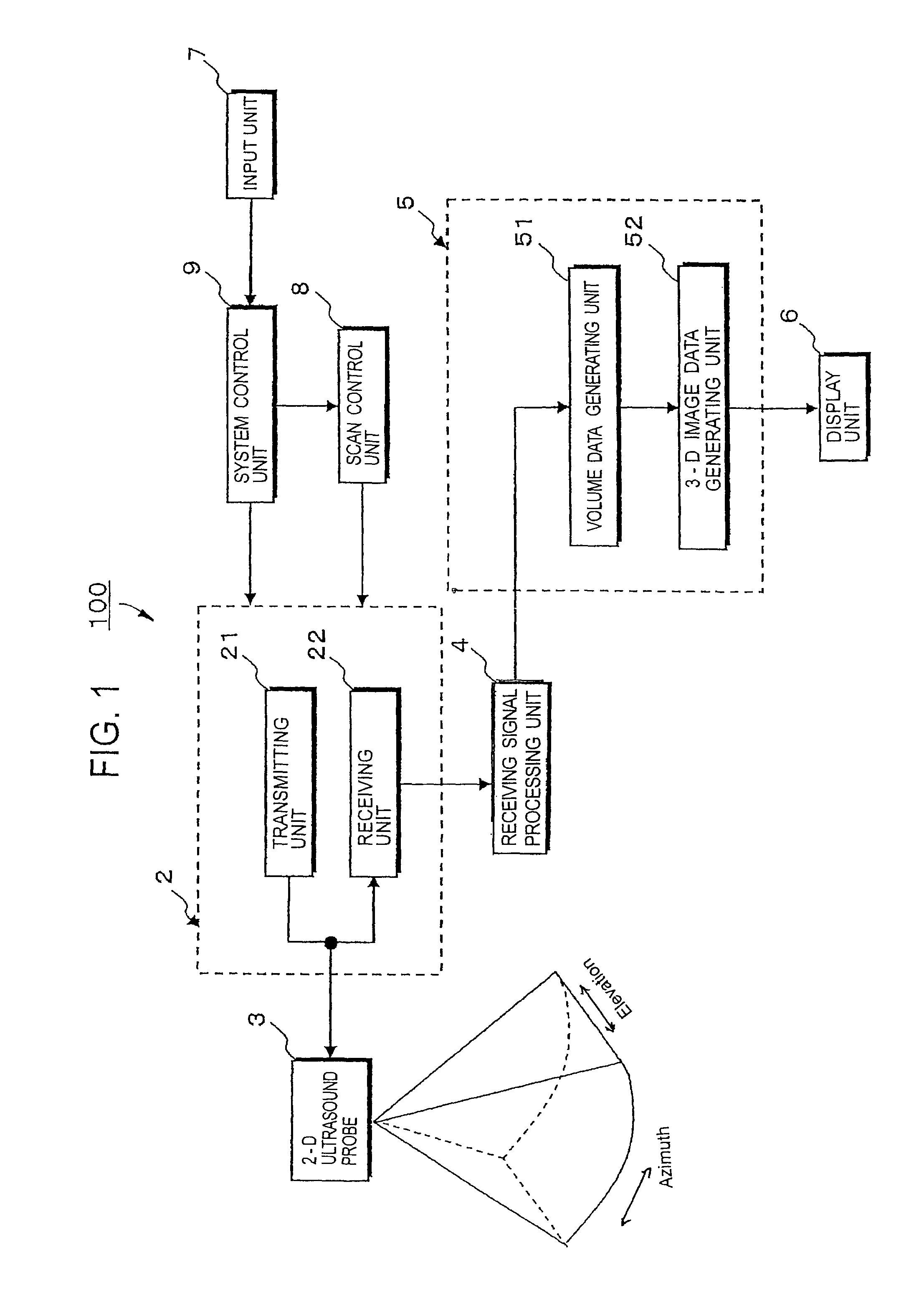
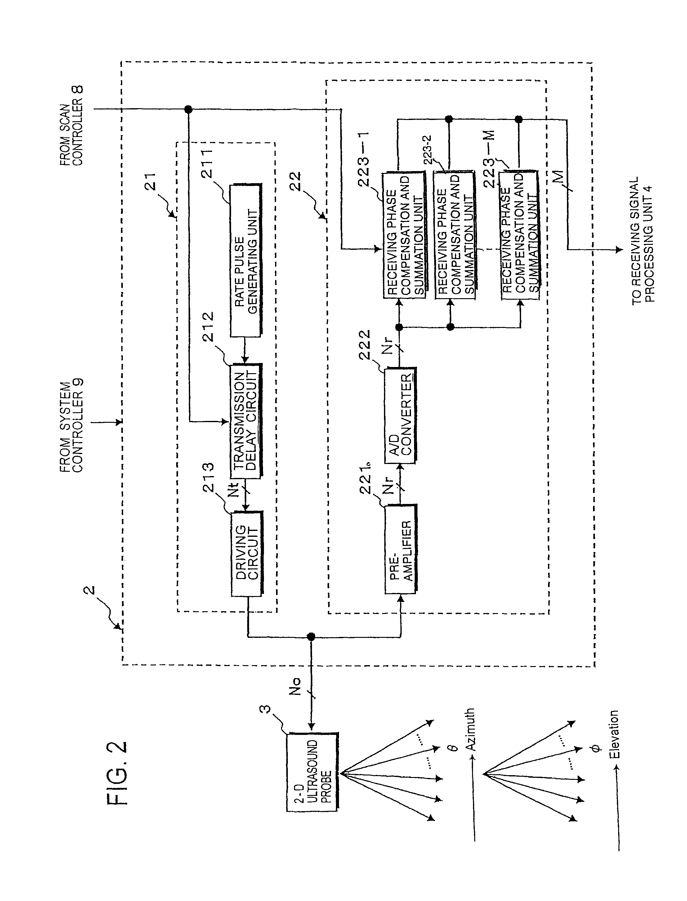
[0051]In the following embodiment of the ultrasound diagnosis apparatus consistent with the present invention, a sector scan type ultrasound diagnosis apparatus is explained so as to apply the parallel simultaneous reception method. The invention can a...


PUM


Abstract

An ultrasound diagnosis apparatus that can generate and display 3D ultrasound image data of superior image quality in real time is provided. To achieve a high volume rate for acquiring 3D ultrasound image data, the ultrasound diagnosis apparatus performs 3D scans on a 3D region of an object while sequentially shifting a transmission / reception group that is comprised of each of the transmitting acoustic fields and more than five parallel simultaneous reception beam directions corresponded to each of the transmitting acoustic fields at a prescribed angular distance Δξ0 along the θ (azimuth) direction and the φ (elevation) direction.

Description

CROSS-REFERENCE TO RELATED APPLICATIONS[0001]This application claims priority from, and the benefit of, Japanese Patent Application No. 2008-167948, filed on Jun. 26, 2008, the contents of which are expressly incorporated herein by reference in their entirety.BACKGROUND OF THE INVENTION[0002]A. Field of the Invention[0003]The present invention relates to an ultrasound diagnosis apparatus for displaying 3-dimensional (3D) images by performing a 3D scan over a target region by using a 2-dimensional (2D) array ultrasound probe. More particularly, the present invention relates to a parallel simultaneous reception-type ultrasound diagnosis apparatus that can acquire 3D image data (hereinafter, “volume data”) with an increased acquisition rate of 3D ultrasound image data (volume rate) by eliminating heterogeneous sensitivities among parallel simultaneous receiving beams.[0004]B. Background of the Invention[0005]An ultrasound image diagnosis apparatus transmits and receives ultrasound thro...

Claims


Application Information

Patent Timeline
Patent Type & Authority Patents(United States)
IPC IPC(8): G01S15/89G01S7/52A61B8/13A61B8/06A61B8/00A61B8/08
CPCA61B8/13A61B8/06G01S7/52085G01S15/8979G01S15/8993G01S7/52095A61B8/483
Inventor NAKATA, KAZUHITO
Owner TOSHIBA MEDICAL SYST CORP
Why Eureka
Try Eureka