
Heating apparatus fixing apparatus and image forming apparatus

a technology of fixing apparatus and fixing roller, which is applied in the direction of electric/magnetic/electromagnetic heating, manufacturing tools, instruments, etc., can solve the problems of uneven image quality, degraded image quality, and sharp changes in the temperature of the fixing roller, so as to prevent an overshoot of temperature, improve reaction speed, and reduce the size of the thermistor

Inactive Publication Date: 2004-08-05
RICOH KK
View PDF5 Cites 35 Cited by
  • Summary
  • Abstract
  • Description
  • Claims
  • Application Information

AI Technical Summary

Benefits of technology

The present invention aims to solve the problems of a fixing apparatus, heating apparatus, and image forming apparatus that use a mass capacitor as an auxiliary power supply. These problems include the need for high power to shorten the starting time of the heating roller, the poor thermal conductivity of the elastic layer of the heating roller which causes uneven image quality, the difficulty in increasing the maximum current of the halogen heater, the need for a large number of capacitor cells to achieve high power, the high cost and safety hazards associated with the use of a large auxiliary power supply, and the reduction of the output voltage to prevent overshooting of the temperature. The invention aims to provide a heating apparatus, fixing apparatus, and image forming apparatus that can heat with little temperature change, quickly raise the temperature, provide high-definition and high-speed output, improve separation characteristics from a toner image, and reduce the size and cost of the auxiliary power supply.

Problems solved by technology

However, in a case that an auxiliary power supply employing a mass capacitor is used, and the fixing roller temperature is controlled by turning on / off the power supply, high power is supplied to the heater, which causes sharp changes of the temperature of the fixing roller, as shown by FIG. 4.
Accordingly, when the temperature of the fixing roller changes in the middle of fixing an image on the heating target, unevenness of image quality develops, and the image quality is degraded.
However, the elastic layer has poor thermal conductivity, and as many sheets are processed, the surface temperature of the heating roller tends to fall, causing poor fixing.
Thus, the poor thermal conductivity of the elastic layer of the heating roller works against the speed.

Method used


Image

  • Heating apparatus fixing apparatus and image forming apparatus
  • Heating apparatus fixing apparatus and image forming apparatus
  • Heating apparatus fixing apparatus and image forming apparatus

Examples


embodiment 11

[0073] FIG. 17 is a schematic diagram showing the circuit configuration of the fixing apparatus of the present invention.

embodiment 12

[0074] FIG. 18 is a schematic diagram showing the circuit configuration of the fixing apparatus of the present invention.

embodiment 13

[0075] FIG. 19 is a schematic diagram showing the auxiliary power supply of the present invention.

[0076] FIG. 20 is a table showing experimental values about an influence of an electric current to a human body according to "Electrician's Text" published by The Japan Electric Association.


PUM

PropertyMeasurementUnit
thicknessaaaaaaaaaa
timeaaaaaaaaaa
voltageaaaaaaaaaa

Abstract

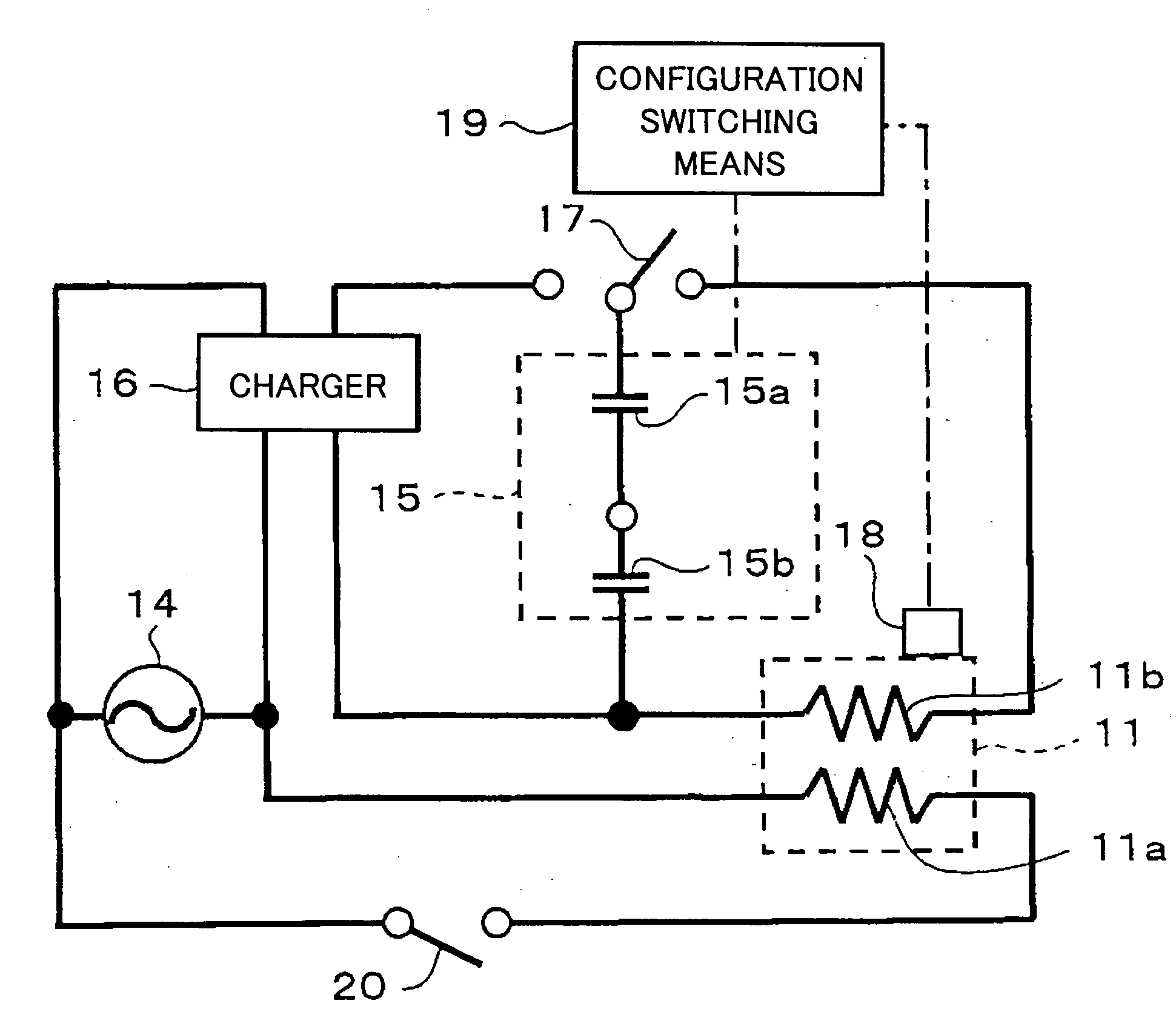
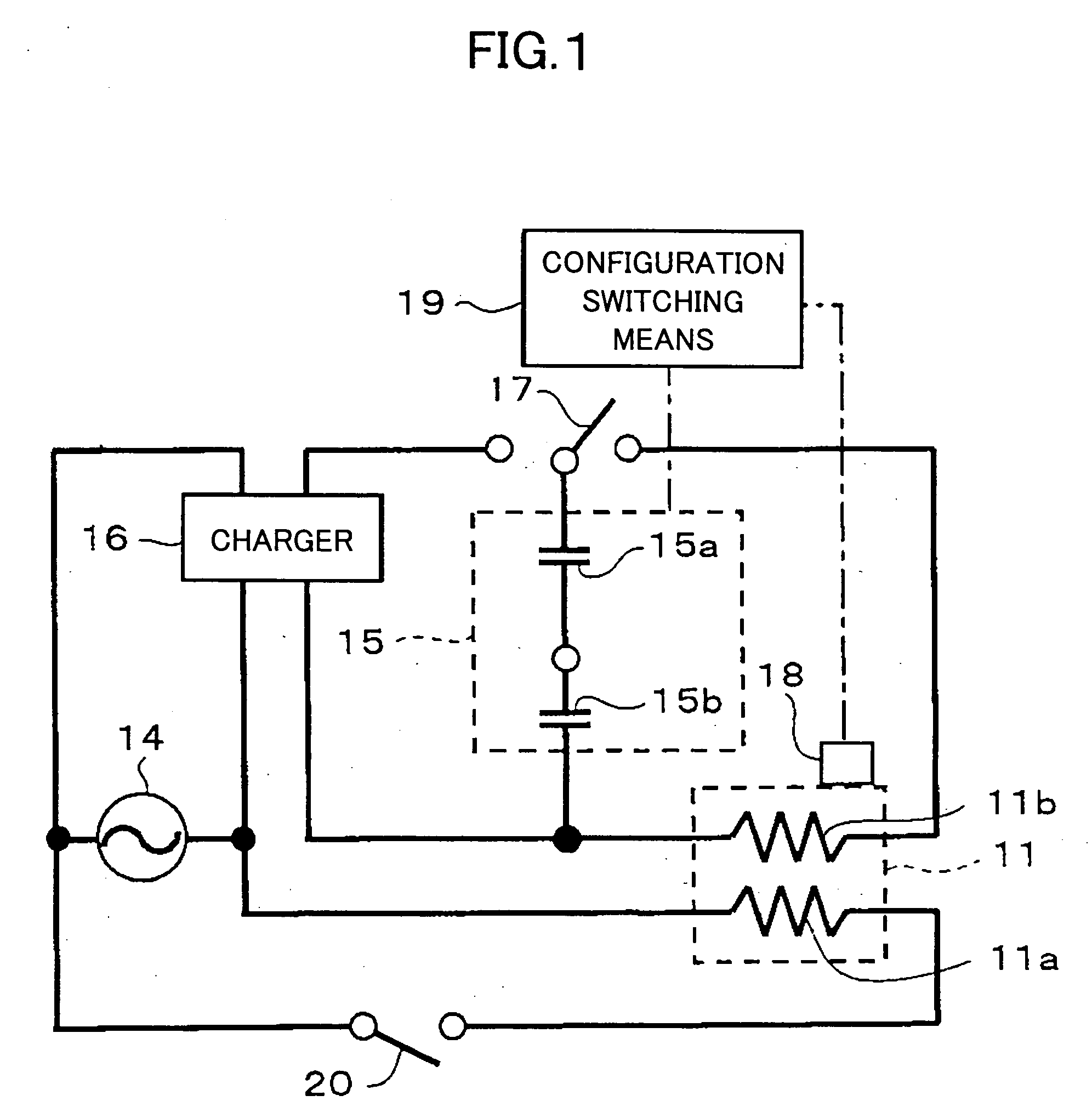
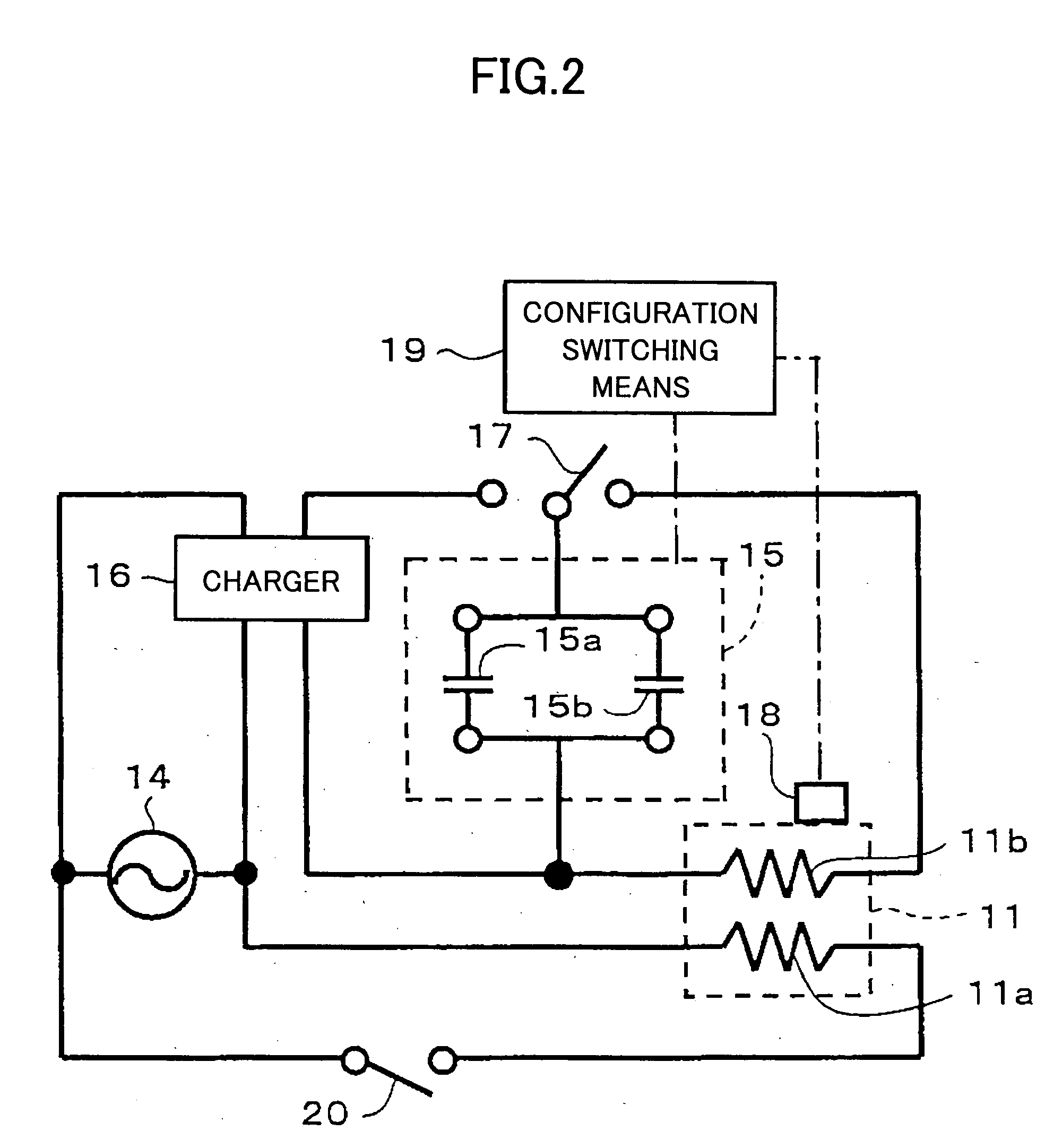
A heating apparatus is disclosed by which a problem, in which the temperature of a fixing roller tends to sharply change when a mass capacitor is employed as an auxiliary power supply, is solved. The heating apparatus includes a heating roller (11) that is heated by heating units (11a and 11b), a main power supply (14) that supplies power from an external power supply to the main heating unit (11a), and an auxiliary power supply (15) that supplies power to the auxiliary heating unit (11b). The auxiliary power supply (15) further includes a mass capacitor that consists of multiple capacitor cells (15a and 15b), which are charged by the external power supply. The connection mode of the capacitor cells is changed at least at the time of electric discharge.

Description

[0001] 1. Field of the Invention[0002] The present invention relates to heating apparatuses for heating various targets, such as paper and a film; fixing apparatuses; image forming apparatuses, such as a copying apparatus, a printer, and a facsimile apparatus.[0003] 2. Description of the Related Art[0004] Image forming apparatuses, such as a copying apparatus, a printer, and a facsimile apparatus, include a process for forming an image on a heating target, such as a sheet of regular paper and OHP paper. In such image forming apparatuses, although various image formation methods are employed, an electro-photographic method is widely adopted from viewpoints of speed, image quality, cost, and so on.[0005] In the electro-photographic method, a toner image that is to be fixed is formed on the heating target, such as a sheet of regular paper and OHP paper, and a fixing process fixes the toner image on the heating target by heat and pressure applied by a fixing apparatus. As the fixing app...

Claims


Application Information

Patent Timeline
Patent Type & Authority Applications(United States)
IPC IPC(8): G03G15/20
CPCG03G2215/20G03G15/80G03G15/2039
Inventor KISHI, KAZUHITOKONNO, ERIKO
Owner RICOH KK
Learn More