Optical multilayer film and image display device

Active Publication Date: 2008-07-31
FUJIFILM CORP
View PDF6 Cites 38 Cited by
  • Summary
  • Abstract
  • Description
  • Claims
  • Application Information

AI Technical Summary

Benefits of technology

[0015]According to the present invention, the first adhesion layer, the second adhesion layer, and the surface layer are stacked on the base material formed of polyester in this order from a side of the base material, thus constituting a multilayer structure. Thereby, it is possible to obtain the optical multilayer film in which the adhesion strength is kept at a high level between the layers, and the occurrence of rainbow unevenness is prevented. Moreover, the image display device capable of achieving excellent displaying quality can be obtained with use of the optical multilayer film as the component thereof.
[0016]Note that in order to reduce the degree of reflection of light on the antireflection film, it is recent trend that the refractive index of the hard coat layer is increased. In a case where the refractive index of the hard coat layer is increased, it is necessary to increase the refractive index of the adhesion layer for the purpose of preventing the rainbow unevenness (in this case the adhesion layer has a single-layered

Problems solved by technology

However, in a case where adhesive strength between the base material and the upper layer is low, the upper layer may be peeled from the base material, thus causing light leakage and making it impossible to prevent light from reflecting.
Therefore, the adhesive strength is important in the optical multilayer film, however, it is difficult to enhance the adhesive strength up to a predetermined level since the adhesive strength tends to be easily affected by material composition of the base material and the upper layer, irregularities on the contact surface, formation condition of each layer, and the like.
Further, when light is reflected on the interfaces, the reflected light interfere with each other to cause a phenomenon in which rainbow color is appeared (rainbow unevenness).
Accordingly, displaying quality in using the optical multilayer film dras

Method used


Image

  • Optical multilayer film and image display device
  • Optical multilayer film and image display device

Examples


Example

Example 1

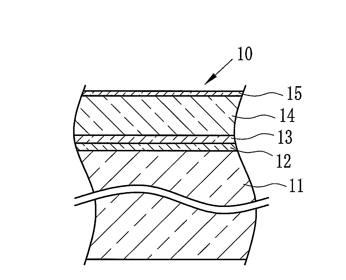
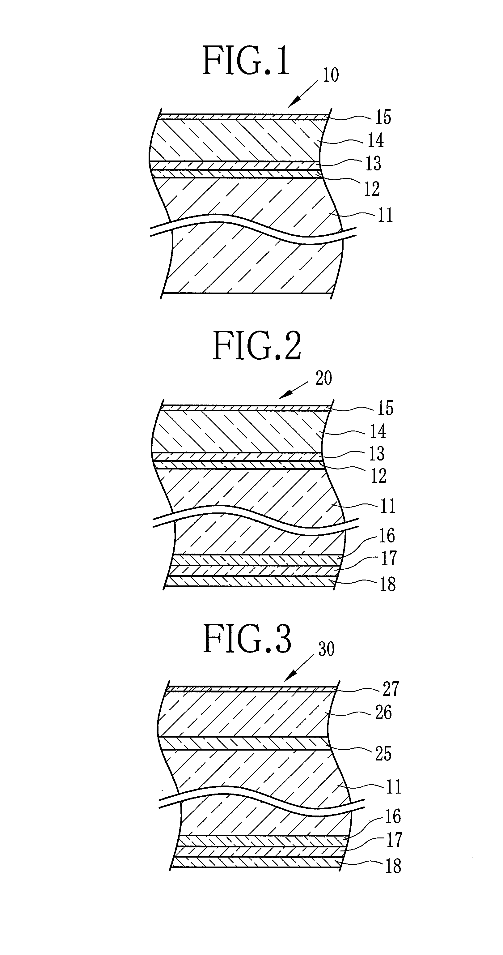
[0080]In this example, in accordance with the following procedure, the multilayer film shown in FIG. 1 was formed.

[0081][Base Material]

[0082]Polyethylene terephthalate (hereinafter referred to as PET) having inherent viscosity of 0.66 was synthesized by polycondensation reaction. The catalyst used in the reaction was antimony trioxide. The PET was dried until the water content thereof became 50 ppm or less, and thereafter melted in an extruder having a heater set at the temperature of 280 to 300° C. Next, the melted PET was discharged onto a chill roll to which electrostatic charge was applied from a die section, thus obtaining an amorphous film. Subsequently, the amorphous film was stretched by 2.9 times in the longitudinal direction of the film, and further stretched by 4.0 times in the width direction thereof, thus completing the biaxially stretching and producing the base material 11 having the thickness of 150 μm. Note that the refractive index η1 of the base material ...

Example

Example 2

[0098]As shown in Table 1, experiment was performed in the same manner as Example 1 except that the coating liquid A in Example 1 was substituted by a coating liquid C and the coating liquid B in Example 1 was substituted by a coating liquid D in Example 2.

[0099][Coating Liquid C]

[0100]Each of the materials whose application amount of solid content is as follows is mixed together to prepare the coating liquid C.

Polyurethane52.0 (mg / m2) Carbodiimide compound10.4 (mg / m2) Surfactant A0.5 (mg / m2)Surfactant B1.0 (mg / m2)Tin oxide dispersion liquid110.0 (mg / m2) 

[0101][Coating Liquid D]

[0102]Each of the materials whose application amount of solid content is as follows is mixed together to prepare the coating liquid D.

Polyurethane47.0 (mg / m2) Carbodiimide compound9.4 (mg / m2)Surfactant A0.5 (mg / m2)Surfactant B1.0 (mg / m2)Titanium oxide dispersion liquid (Dispersion66.0 (mg / m2) liquid in which titanium oxide fine particleare dispersed in water)Silica dispersion liquid1.2 (mg / m2)Carnaub...

Example

Example 3

[0103]As shown in Table 1, experiment was performed in the same manner as Example 1 except that the coating liquid A in Example 1 was substituted by a coating liquid E and the coating liquid B in Example 1 was substituted by a coating liquid F in Example 3.

[0104][Coating Liquid E]

[0105]Each of the materials whose application amount of solid content is as follows is mixed together to prepare the coating liquid E.

Acrylic resin73.0 (mg / m2)Carbodiimide compound14.6 (mg / m2)Surfactant A 0.5 (mg / m2)Surfactant B 1.0 (mg / m2)Tin oxide dispersion liquid14.0 (mg / m2)

[0106][Coating Liquid F]

[0107]Each of the materials whose application amount of solid content is as follows is mixed together to prepare the coating liquid F.

Polyester58.0 (mg / m2)Carbodiimide compound11.6 (mg / m2)Surfactant A 0.5 (mg / m2)Surfactant B 1.0 (mg / m2)Tin oxide dispersion liquid56.0 (mg / m2)Silica dispersion liquid 1.2 (mg / m2)Carnauba wax 3.0 (mg / m2)


PUM


Abstract

A first adhesion layer and a second adhesion layer are formed on a base material formed of polyester biaxially stretched in this order from the side of the base material. Additionally, a hard coat layer and an antireflection layer are formed on the second adhesion layer to form a multilayer film. When refractive indices of the base material, the first adhesion layer, the second adhesion layer, and the hard coat layer are η1, η2, η3, and η4, respectively, the refractive indices are adjusted so as to satisfy the following formulae (1) to (3) to prevent rainbow unevenness.
(η1/η4)1/2×0.95≦η2/η3≦(η1/η4)1/2×1.05   (1)
η1<η4   (2)
η2<η3   (3)
The two adhesion layers can enhance the adhesive strength with the base material.

Description

FIELD OF THE INVENTION[0001]The present invention relates to an optical multilayer film, and an image display device such as a liquid crystal display (LCD), a plasma display (PDP), an organic electroluminescence display (organic EL display), surface-conduction electron-emitter display (SED), and a cathode ray tube display (CRT display) using the optical multilayer film as a component of the image display device.BACKGROUND OF THE INVENTION[0002]In accordance with an increase in demand for an image display device such as a LCD, a PDP, an organic EL display, a SED, and a CRT display, demand for an optical film as a main component of the image display device has been rapidly increasing for the purpose of obtaining high-quality image thereof. The optical film is a film provided with various optical functions for achieving prevention of reflection of external light, enlargement of viewing angle, correction of optical unevenness, and the like.[0003]The optical film is generally a multilaye...

Claims


Application Information

Patent Timeline
IPC IPC(8): G02B1/10
CPCG02B1/111
Inventor KOBAYASHI, TAKASHISUZUKI, KATSUYOSHI
Owner FUJIFILM CORP
Why Eureka
Try Eureka