Charged particle beam irradiating apparatus

a charge particle and beam irradiation technology, applied in the direction of beam deviation/focusing by electric/magnetic means, instruments, therapy, etc., can solve the problems of unevenness or reduction in a peripheral portion of the dose distribution, complex control process, and ineffective above-mentioned methods, so as to prevent unevenness or reduction

Active Publication Date: 2012-04-10
SUMITOMO HEAVY IND LTD
View PDF11 Cites 35 Cited by
  • Summary
  • Abstract
  • Description
  • Claims
  • Application Information

AI Technical Summary

Benefits of technology

[0007]Therefore, an object of the invention is to provide a charged particle beam irradiating apparatus capable of simply preventing unevenness or reduction in a peripheral portion of the dose distribution of a charged particle beam.

Problems solved by technology

However, in the above-mentioned charged particle beam irradiating apparatus, there is a concern that unevenness or reduction will occur in a peripheral portion of the dose distribution of the irradiated charged particle beam (hereinafter, simply referred to as a ‘dose distribution’).
However, in this case, the scanning method needs to control the intensity of the charged particle beam at a high speed, and the control process is complicated.
Therefore, the above-mentioned method is not effective.

Method used


Image

  • Charged particle beam irradiating apparatus
  • Charged particle beam irradiating apparatus
  • Charged particle beam irradiating apparatus

Examples


Embodiment Construction

[0028]Hereinafter, exemplary embodiments of the invention will be described in detail with reference to the accompanying drawings. In the following description, the same or equivalent components are denoted by the same reference numerals, and a repetitive description thereof will be omitted.

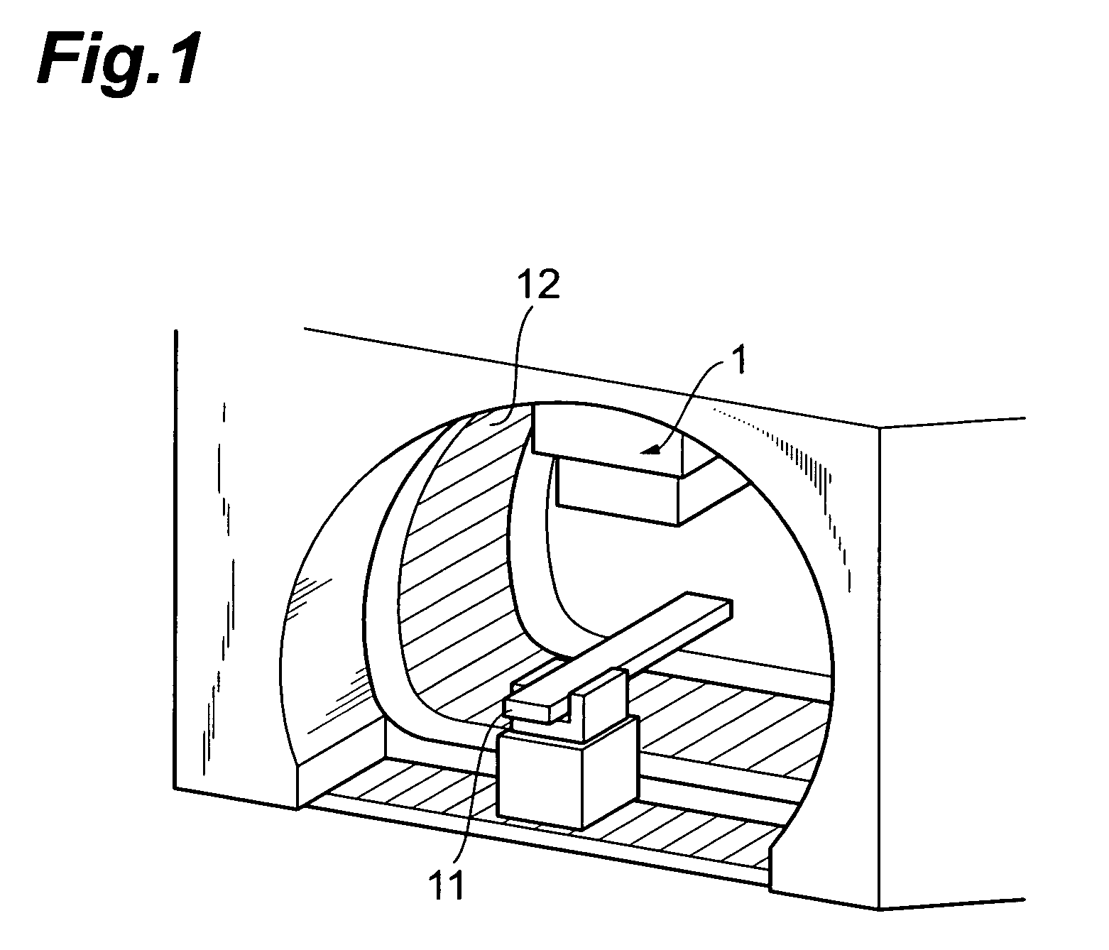
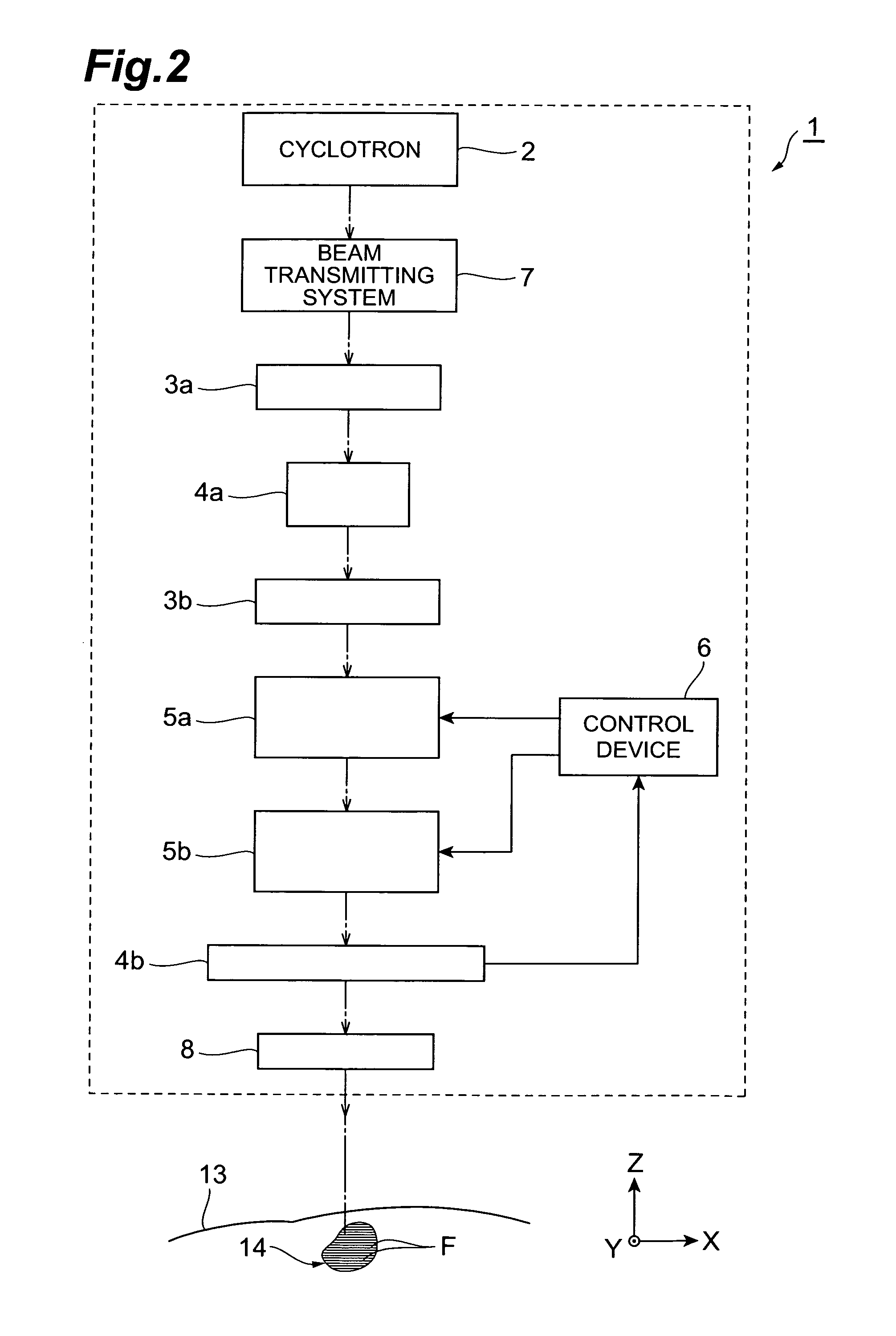
[0029]First, a charged particle beam irradiating apparatus according to a first embodiment of the invention will be described. FIG. 1 is a perspective view illustrating the charged particle beam irradiating apparatus according to the first embodiment of the invention, and FIG. 2 is a diagram schematically illustrating the structure of the charged particle beam irradiating apparatus shown in FIG. 1. As shown in FIG. 1, a charged particle beam irradiating apparatus 1 uses a scanning method, and is provided on a rotating gantry 12 that is provided so as to surround a treatment table 11. The charged particle beam irradiating apparatus 1 can be rotated around the treatment table 11 by the rotating gan...


PUM


Abstract

The present invention provides a charged particle beam irradiating apparatus capable of simply preventing unevenness or reduction in a peripheral portion of the dose distribution of a charged particle beam.A charged particle beam irradiating apparatus includes scanning electromagnets that scan a charged particle beam and a control device that controls the operations of the scanning electromagnets. In the charged particle beam irradiating apparatus, the control unit changes a scanning speed when the charged particle beam is irradiated along an irradiation line such that a peripheral portion of the dose distribution of the charged particle beam is corrected.

Description

BACKGROUND OF THE INVENTION[0001]1. Field of the Invention[0002]The present invention relates to a charged particle beam irradiating apparatus using a scanning method.[0003]Priority is claimed on Japanese Patent Application No. 2008-87123, filed Mar. 28, 2008, the content of which is incorporated herein by reference.[0004]2. Description of the Related Art[0005]For example, JP-A-2002-22900 discloses a charged particle beam irradiating apparatus using a scanning method. The charged particle beam irradiating apparatus includes a scanning electromagnet that scans a charged particle beam and a control unit that controls the operation of the scanning electromagnet, and continuously irradiates the charged particle beam along an irradiation line in an irradiation field that is set in an object to scan the irradiation field.[0006]However, in the above-mentioned charged particle beam irradiating apparatus, there is a concern that unevenness or reduction will occur in a peripheral portion of t...

Claims


Application Information

Patent Timeline
Patent Type & Authority Patents(United States)
IPC IPC(8): H01J3/26
CPCA61N5/10A61N5/1043A61N2005/1087A61N5/1048A61N5/01
Inventor TACHIKAWA, TOSHIKIASABA, TORUOCHI, TOSHIAKI
Owner SUMITOMO HEAVY IND LTD
Why Eureka
Try Eureka