
Image processing method and image processing apparatus

a technology of image processing and image processing apparatus, applied in the direction of electrical apparatus, instruments, computing, etc., can solve the problems of wasteful data transfer, long wait time, long decoding time, etc., and achieve the effect of suppressing wasteful data transfer

Active Publication Date: 2010-02-09
CANON KK
View PDF9 Cites 4 Cited by
  • Summary
  • Abstract
  • Description
  • Claims
  • Application Information

AI Technical Summary

Benefits of technology

The present invention provides an image processing method and apparatus that can access a required partial image and suppress wasteful data transfer. This is achieved by calculating the occupation ratio of a requested partial area to the entire image and transmitting encoded data divided into a plurality of tiles based on the ratio. The method can also include analyzing the request, calculating the size of the requested area, and transmitting the encoded data accordingly. The invention allows for efficient image processing and reduces data transfer load.

Problems solved by technology

However, when image data with a large pixel size which is taken by the aforementioned digital camera in recent years is to be downloaded from a server every time the user selects to display it in an enlarged scale, a very long wait time is required until that image is displayed on a client terminal.
Therefore, as the number of tiles including areas required in display increases, the number of times of file seek operations increases, resulting in a long decode time.
For this reason, upon decoding the entire image with a low resolution (small image size), a very long decode time is required although its size is small (resolution is low).
However, when the number of tiles of an image is decreased without careful consideration, such data becomes hard to handle in the server / client.

Method used


Image

  • Image processing method and image processing apparatus
  • Image processing method and image processing apparatus
  • Image processing method and image processing apparatus

Examples


first embodiment

[0058]The first embodiment will explain a method in which upon reception of a request from a client, a server which holds a plurality of already generated JPEG2000 files analyzes that request, generates response data according to the request from a designated JPEG2000 encoded image, and transmits the response data to the client.

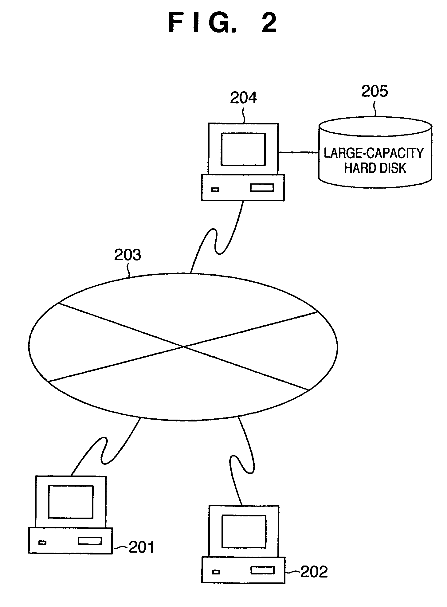
[0059]A case will be described below wherein the user who operates the client opens a given home page on the Internet, displays a thumbnail image according to link information used to acquire a JPEG2000 encoded image displayed there, then displays the entire image, and further displays a partial area of the image in an enlarged scale. In order to attain such image display, the client acquires data from the server using the mechanism of JPIP. Assume that a data transmission unit by JPIP is a packet.

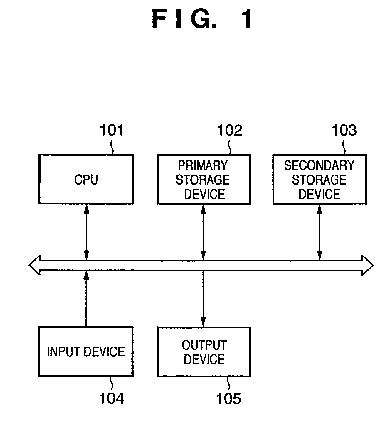
[0060]FIG. 1 is a schematic block diagram showing the arrangement of a computer required to implement the server / client system according to the first embodiment of ...

second embodiment

[0175]In the first embodiment described above, images held by the server 204 assume JPEG2000 encoded image data in each of which an image is divided into a large number of tiles in consideration of random accessibility.

[0176]Note that some systems may use many images which are kept in relatively small sizes in list display in most cases, and only several ones of these images may undergo operations such as enlargement or the like. In such case, the server may hold JPEG2000 encoded images with a small number of divided tiles, and the number of tiles may be increased as needed. Hence, in this embodiment, each JPEG2000 encoded image data held by the server has encode conditions:

[0177]Maximum image size: 4064×2752 pixels

[0178]Tile size: 256×256 pixels

[0179]Number of tiles: 176 (=16×11)

[0180]Number of resolution levels: 5

[0181]Image sizes of respective resolution levels:

[0182]Resolution level 4: 4064×2752 pixels (tile size: 256×256 pixels)

[0183]Resolution level 3: 2032×1376 pixels (tile s...

third embodiment

[0196]In the first and second embodiments described above, data held by the server 204 have common encode conditions. In some systems, common encode conditions may be used. However, in a system to which various images are uploaded, it is difficult to use common encode conditions of the images.

[0197]In this embodiment, assume that image data of various encode conditions are held on the server side. Assume that the arrangements of the server and client and that of the server / client system in the third embodiment are the same as those in the first and second embodiments shown in FIGS. 1 and 2.

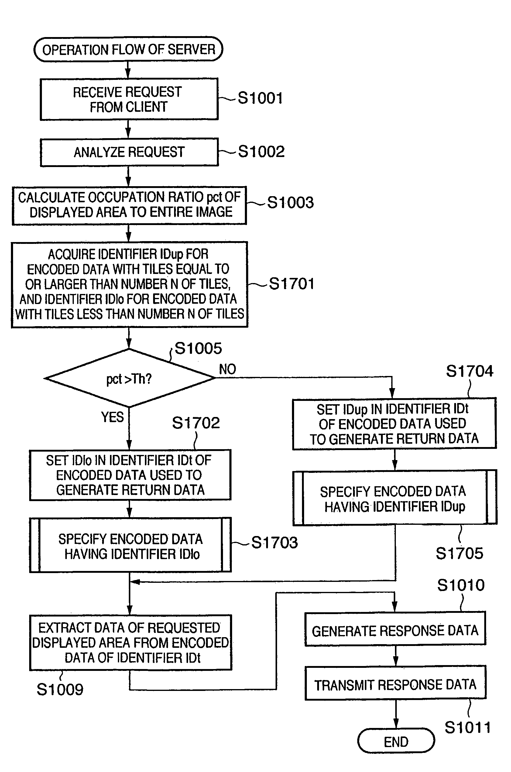
[0198]In this embodiment, the server 204 calculates an occupation ratio pct of the displayed area to the entire image on the basis of the request from the client, and compares the calculated ratio pct with a predetermined threshold Th as in the first and second embodiments. As a result, if the value of the ratio pct is larger than the threshold Th, i.e., if the occupation ratio of the displayed ar...


PUM


Abstract

There are provided an image processing method and image processing apparatus, which can suitably access a necessary partial image, and can suppress wasteful data transfer by returning data with a small number of tiles for a thumbnail image of a low resolution or the like so as to reduce the number of times of file seek operations, and returning data with a large number of tiles for an image of a high resolution to be returned in response to an enlargement request. To this end, a server encoded data fragmentarily transmits encoded data which is hierarchically encoded by dividing an image into a plurality of tiles in response to a request from a client. The server calculates an occupation ratio of the displayed area of the image requested from the client to the entire image. When the ratio is equal to or lower than a threshold, the server selects encoded data divided to have a larger number of tiles. Otherwise, the server selects encoded data with a smaller number of tiles. The server extracts data corresponding to the displayed area from the selected encoded data, and transmits the extracted data to the client.

Description

FIELD OF THE INVENTION[0001]The present invention relates to a technique for transmitting an image which is encoded after being divided into a plurality of tiles, and a technique for changing the number of tiles to be divided of the image as needed.BACKGROUND OF THE INVENTION[0002]In recent years, the number of pixels to be handled by digital cameras which have prevailed remarkably has become increasingly huge, and general-purpose cameras having, e.g., about two to five million pixels are popular. As digital cameras for professionals, those of 10-million pixel classes are beginning to prevail, and higher resolution will be required in the future.[0003]On another front, users who enjoy uploading images taken with digital cameras to an online album service on the Internet are increasing. In such systems, various types of image browser software are available. In general, a list of thumbnail images is displayed, and the user selects an image to be displayed in an enlarged scale from the...

Claims


Application Information

Patent Timeline
Patent Type & Authority Patents(United States)
IPC IPC(8): G06K9/36G06K9/46G06T9/00H04N1/41H04N1/413H04N19/00H04N19/33H04N19/40H04N19/46H04N19/58H04N19/70
CPCH04N19/64
Inventor ISHIKAWA, TOMOE
Owner CANON KK
Learn More