Heat dissipation assembly

a technology of heat dissipation assembly and assembly plate, which is applied in the direction of air heater, lighting and heating apparatus, and semiconductor/solid-state device details, etc., can solve the problems of easy distortion or even breakage, and the tedious manipulation of screws during installation or removal of the fan

Inactive Publication Date: 2010-02-16
CLOUD NETWORK TECH SINGAPORE PTE LTD
View PDF13 Cites 6 Cited by
  • Summary
  • Abstract
  • Description
  • Claims
  • Application Information

AI Technical Summary

Benefits of technology

[0006]In one embodiment, a heat dissipation assembly includes a heat sink and a fan. The heat sink device has a base and a plurality of fins formed on the base, the fins are parallel with each other, one or more of the fins cooperatively form at least two concave engagement parts. The fan has at least two elastic arms extending from middle positions of two opposite sides of the fan, an engagement hook is formed at an end of the at least two arms. The at least two engagement hooks are engagable with the at least two engagement parts, for fastening the fan on the heat sink device.

Problems solved by technology

However, the holes weaken the heat sink devices, causing them to be easily distorted or even to break.
Furthermore, it is a tedious task to manipulate screws during installation or removal of the fan.

Method used


Image

  • Heat dissipation assembly
  • Heat dissipation assembly
  • Heat dissipation assembly

Examples


Embodiment Construction

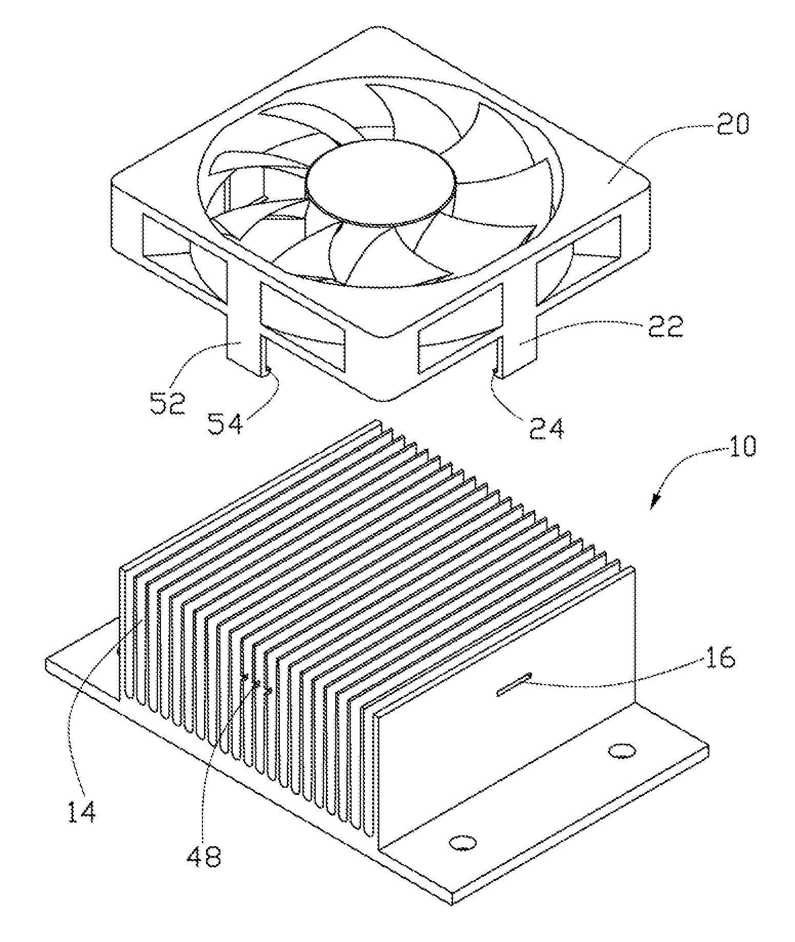
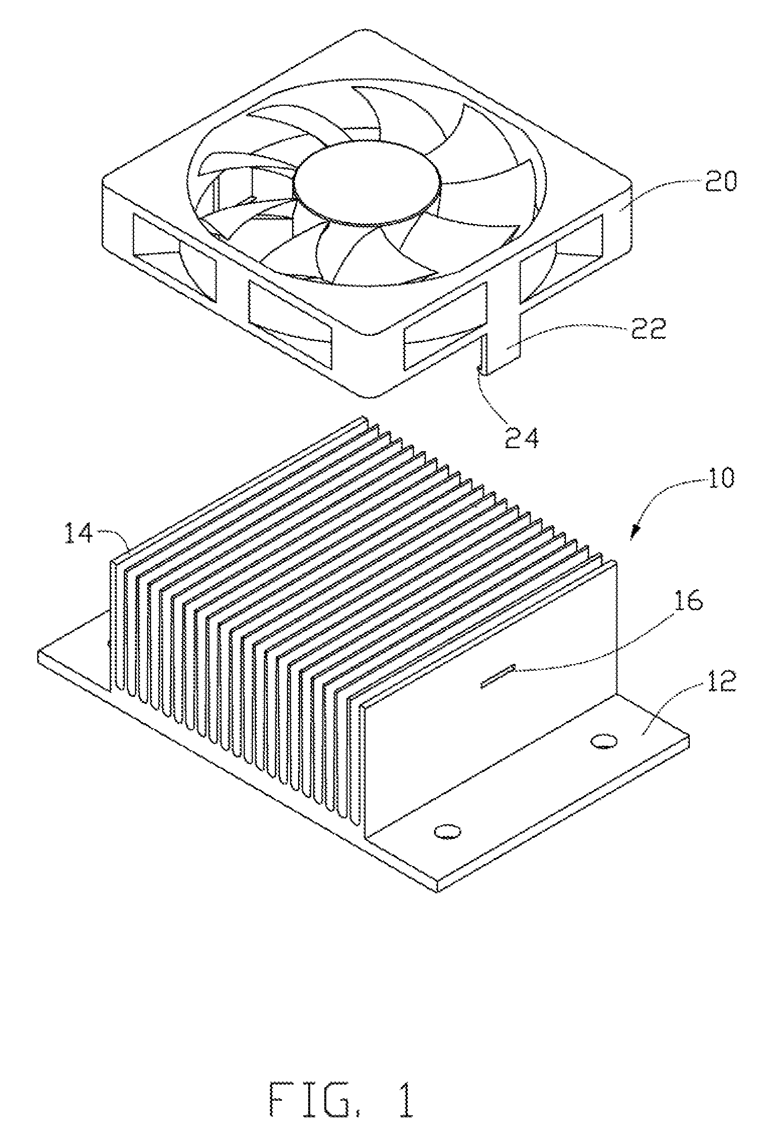
[0014]Referring to FIG. 1, a heat dissipation assembly in accordance with an exemplary embodiment includes a heat sink device 10 and a fan 20.

[0015]The heat sink device 10 includes a base 12 and a plurality of parallel fins 14 extending from the base 12. The fins 14 are generally rectangular. A hole 16 is defined in a middle portion of each of two outer fins 14. The portions bounding the holes 16 respectively form engagement parts. The holes 16 are generally quadrate slots parallel to the base 12, and extend along longitudinal directions of the fins 14.

[0016]The fan 20 is generally rectangular, which includes a pair of elastic arms 22 extending from opposite sides thereof, corresponding to the holes 16 of the fins 14. At an end of each arm 22, a hook 24 is formed. The hooks 24 extend from the arms 22 toward each other.

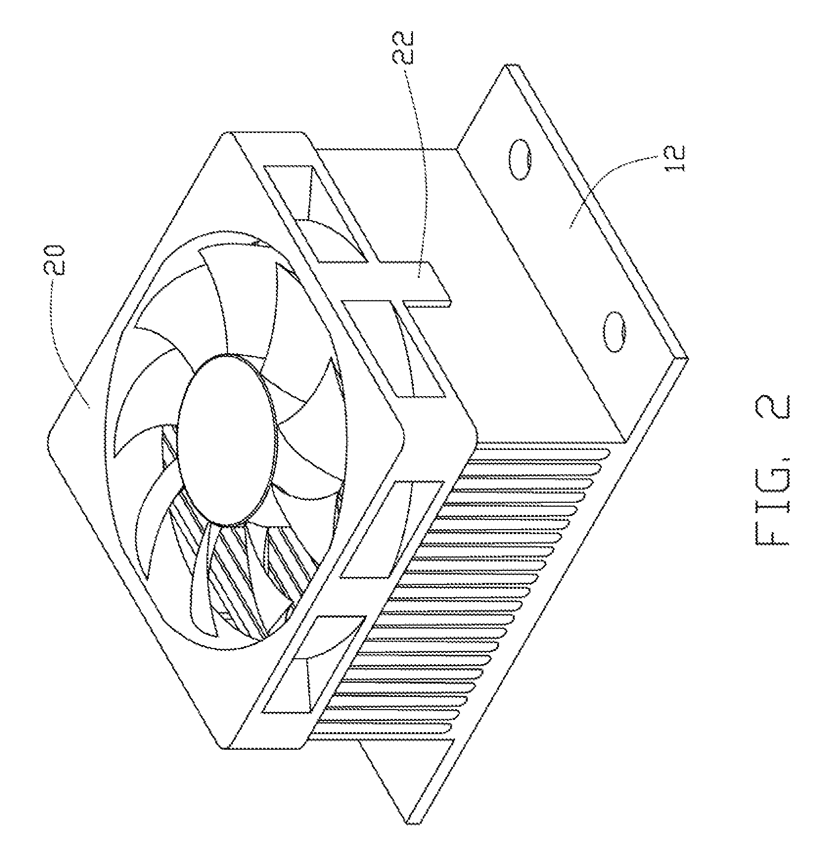
[0017]Referring to FIG. 2, in assembly, the arms 22 of the fan 20 are deformed outwardly with the hooks 24 tightly engaging with the two outer fins 14 respectively, th...


PUM


Abstract

A heat dissipation assembly includes a heat sink and a fan. The heat sink device has a base and a plurality of fins formed on the base, the fins are parallel with each other, one or more of the fins cooperatively form at least two concave engagement parts. The fan has at least two elastic arms extending from middle positions of two opposite sides of the fan, an engagement hook is formed at an end of the at least two arms. The at least two engagement hooks are engagable with the at least two engagement parts, for fastening the fan on the heat sink device.

Description

BACKGROUND[0001]1. Field of the Invention[0002]The present invention relates to a heat dissipation assembly. Particularly, the present invention relates to a heat dissipation assembly for dissipating heat generated by a chip.[0003]2. Description of Related Art[0004]Electronic devices use heat dissipation assemblies for dissipating heat generated by components therein, thus preventing the components from being overheated. Typically, a heat sink device is assembled on top of a heat-generating component, for absorbing heat of the component and radiating the heat to a much larger space, which benefits dissipation of the heat. Furthermore, a fan is fixed on the heat sink device; the fan assists for heat dissipation. The fan and the heat sink device respectively have holes formed on the sides, and screws extend through the holes to fix the fan on the heat sink device.[0005]However, the holes weaken the heat sink devices, causing them to be easily distorted or even to break. Furthermore, i...

Claims


Application Information

Patent Timeline
Patent Type & Authority Patents(United States)
IPC IPC(8): F28F7/00H05K7/20
CPCH01L23/467H01L2924/0002H01L2924/00
Inventor KUO, SZU-WEI
Owner CLOUD NETWORK TECH SINGAPORE PTE LTD
Why Eureka
Try Eureka