
Vehicle light unit with shadow casting feature

a technology for vehicle light and shadow casting, which is applied in the direction of cycle equipment, lighting and heating equipment, optical signals, etc., can solve the problems of obscuring the visibility of the seal, difficult for the light to reach the area where the seal is attached, and plain seals

Inactive Publication Date: 2010-02-16
YAMAHA MOTOR CO LTD
View PDF6 Cites 5 Cited by
  • Summary
  • Abstract
  • Description
  • Claims
  • Application Information

AI Technical Summary

Benefits of technology

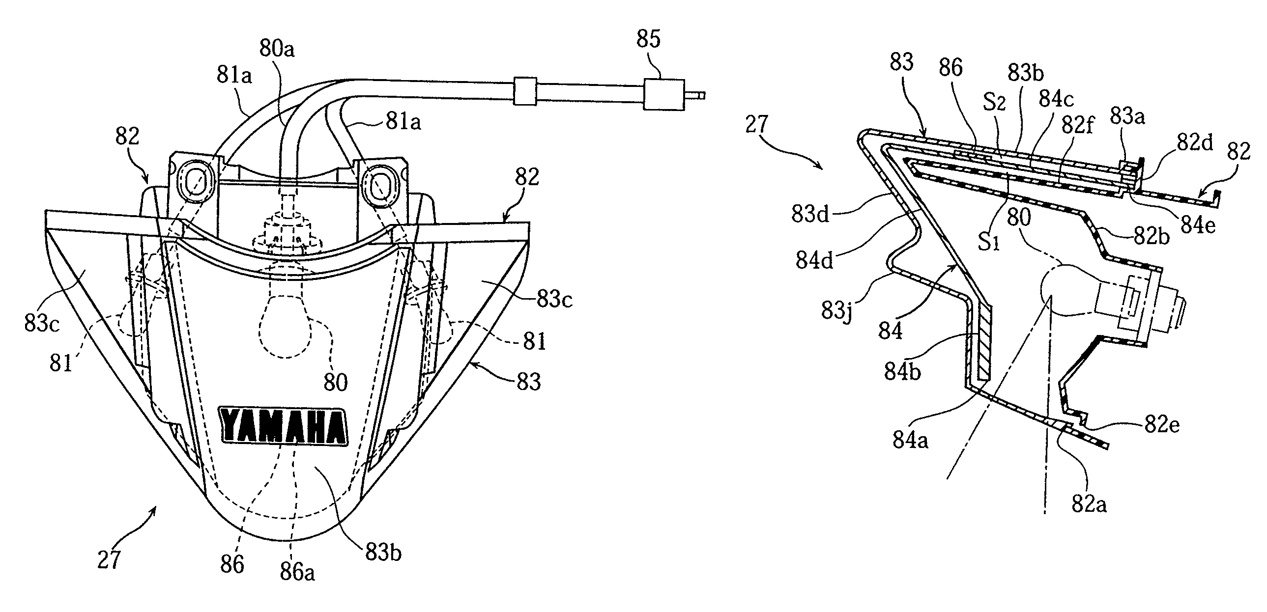
The present invention provides a light unit with an unconventional and distinct external appearance compared to conventional light units. The light unit includes a translucent lens with a shadow-forming surface inside, which casts a shadow on the surface when outside light enters through the lens. The light unit also includes a shadow casting design that blocks some of the light and forms the shadow on the surface. This creates a three-dimensional appearance that gives the impression that the design is floating. The light unit can be used in vehicles and has several advantages over conventional light assemblies.

Problems solved by technology

In this case, the light emitted by the bulb passes through the lens and obscures the visibility of the seal.
In order to increase the visibility of the seal, fine lines can be cut in the lens to make it difficult for the light to reach the area where the seal is attached.
Unfortunately, the fine lines cut in the lens result in the seal having a plain appearance.

Method used


Image

  • Vehicle light unit with shadow casting feature
  • Vehicle light unit with shadow casting feature
  • Vehicle light unit with shadow casting feature

Examples


Embodiment Construction

,” one will understand how the features of the present light unit provide several advantages over conventional vehicle light assemblies.

BRIEF DESCRIPTION OF THE DRAWINGS

[0012]These and other features, aspects and advantages of the present invention will now be described in connection with preferred embodiments of the invention, in reference to the accompanying drawings. The illustrated embodiments, however, are merely examples and are not intended to limit the invention. The following are brief descriptions of the drawings.

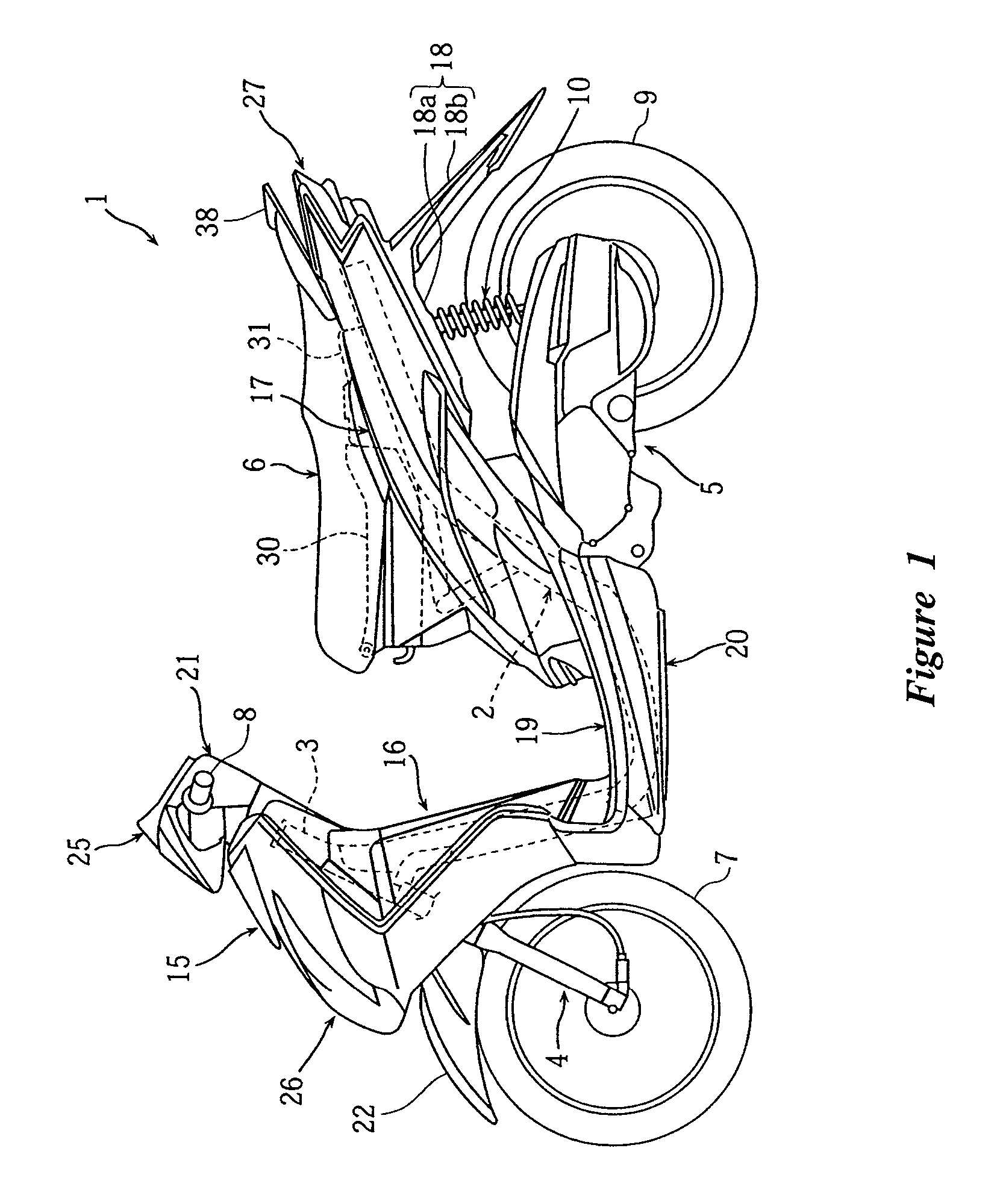
[0013]FIG. 1 is a side view of a motorcycle equipped with a tail lamp unit or light unit configured in accordance with a preferred embodiment of the present invention.

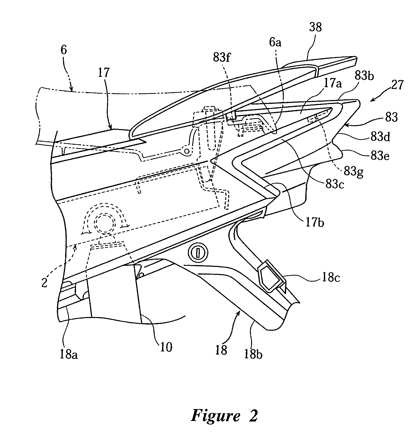
[0014]FIG. 2 is an enlarged partially side view of a rear portion of the motorcycle from FIG. 1 showing the light unit.

[0015]FIG. 3 is a plan view of the rear portion of the motorcycle from FIG. 2.

[0016]FIG. 4 is a plan view of the light unit from FIG. 3 removed from the motorcycle.

[0017]FIG. 5 is a ...


PUM

PropertyMeasurementUnit
translucentaaaaaaaaaa
permeableaaaaaaaaaa
widthaaaaaaaaaa

Abstract

The light unit includes a lens, shadow-forming surface, and a shadow casting surface. Outside light entering the light unit is at least partially blocked by the shadow casting surface so as to cast a shadow on the shadow-forming surface. The shadow casting surface may be embedded within or on a surface of the lens or otherwise supported above the shadow forming surface. The shadow casting design is preferably spaced from the shadow-forming surface.

Description

RELATED APPLICATIONS[0001]The present application is based on and claims priority under 35 U.S.C. § 119(a)-(d) to Japanese Patent Application No. 2006-081941, filed on Mar. 24, 2006, the entire contents of which is hereby expressly incorporated by reference herein.BACKGROUND OF THE INVENTION[0002]1. Field of the Invention[0003]The present invention relates to a light unit for a vehicle.[0004]2. Description of the Related Art[0005]Conventional motorcycles have a tail lamp and lens assembly that is visible from the left and right sides to improve the motorcycle's external appearance (see, for example, Japanese Patent Abstract JP-A-10-100968). In addition, some motorcycles include indicia of the name of the vehicle model or manufacturer. Such indicia often are (but not necessarily limited to) trademarks and / or logos of the manufacturer, and will hereinafter be referred to as a “seal”. The seal commonly is a sticker and is preferably placed in a location that is highly visible. The seal...

Claims


Application Information

Patent Timeline
Patent Type & Authority Patents(United States)
IPC IPC(8): B62J6/00F21W107/17
CPCB60Q1/50B62J6/04
Inventor OHZONO, GEN
Owner YAMAHA MOTOR CO LTD
Learn More