Shaped MRI coil array

a coil array and coil array technology, applied in the field of nuclear magnetic resonance imaging multi-element coil arrays, can solve the problems of low q decoupling, reduced preamp decoupling effect strength, loss of sensitivity, etc., to prevent the increase of coupling, minimize mutual inductance, and minimize mutual inductance

Active Publication Date: 2010-02-16
THE GENERAL HOSPITAL CORP
View PDF14 Cites 45 Cited by
  • Summary
  • Abstract
  • Description
  • Claims
  • Application Information

AI Technical Summary

Benefits of technology

[0011]The present invention is an MRI rf coil array for use in applications where a complex curvature is desired to conform to the shape of a subject to be imaged. More specifically, it includes a substrate formed to have the desired shape and a plurality of coil elements mounted on the surface of the substrate in an overlapping pattern. The overlapping pattern is based on a tiling pattern of regular polygons that cover the surface of the substrate and each coil element is aligned around a center of one of said regular polygons and is sized to overlap adjacent coil elements such that the mutual inductance there between is minimized.
[0012]A general object is to provide a coil array that conforms to a complex surface having a Gaussian curvature which is non-zero. By tiling the complex surface with regular polygons of substantially the same size, corresponding coil elements can be located and sized to follow the complex surface and minimize mutual inductance. Polygons with fewer sides are used at points of higher curvature. Specifically, the incorporation of pentagons into an array of hexagons allows for coil elements of substantially the same size to be arranged on a surface with Gaussian curvature while maintaining the critical overlap between all neighboring coils such their mutual inductance is minimized.
[0013]Another aspect of the present invention is a design which prevents the increase in coupling that occurs with small coil elements. When the coil elements are very small (on the order of 2 inches diameter or less) the capacitor value needed for matching the sample impedance to the 50 Ohm system becomes large. When this capacitor is also used as the basis for the coil decoupling circuit it results in a low Q decoupling circuit, which reduces the strength of the preamp decoupling effect. Even though neighboring coils are overlapped, there is significant coupling between next nearest neighbors, and when preamp decoupling is weak this leads to a loss in sensitivity. The present invention addresses this problem by separating the match functionality and detuning functionality to create a high Q decoupling circuit which results in a stronger preamp decoupling effect, increasing the sensitivity of the receive array.
[0014]Yet another aspect of the present invention is the construction of a high Q coil element for a coil array. It is recognized that for a coil element constructed from a flat strip conductor such as machined circuit board or flexible Pyralux circuit board material, if the track width is kept the same, as the number of coil elements in an array increases and their size decreases, the percentage of copper covering the surface increases. The copper in the other coil elements creates a loading effect on each coil element, reducing the unloaded Q and adding noise. It has been discovered that by manufacturing the coil element with a substantially round wire instead of the conventional printed circuit board ribbon conductor, this drop in unloaded Q is ameliorated.
[0015]Another aspect of the invention is the incorporation of a circuit between the preamp and the coil element which allows any given element to couple with the transmit B1 RF field in a controlled way to allow flexible reshaping of the transmit B1 field.
[0017]The invention is used in connection with MRI scanners. It may include a helmet-type coil covered with surface coil elements each of which can both transmit and receive an RF signal at the operating frequency of the scanner. It may also include a larger helmet-like structure which only creates a transmit B1 field and has separate receive coils within it. It requires additional hardware to control the RF signal fed to each coil element, either by adjusting the phase and amplitude of the signal to each element or by sending different RF waveforms to each element as with Transmit SENSE. The device allows greater homogeneity of the B1 field in high field MRI, or for focused RF excitation of only particular regions of interest to reduce the overall SAR load in the subject.

Problems solved by technology

When this capacitor is also used as the basis for the coil decoupling circuit it results in a low Q decoupling circuit, which reduces the strength of the preamp decoupling effect.
Even though neighboring coils are overlapped, there is significant coupling between next nearest neighbors, and when preamp decoupling is weak this leads to a loss in sensitivity.

Method used


Image

  • Shaped MRI coil array
  • Shaped MRI coil array
  • Shaped MRI coil array

Examples


Embodiment Construction

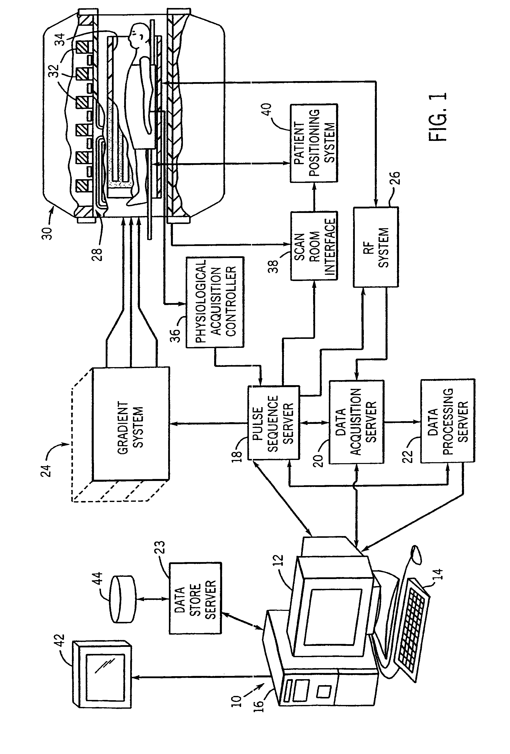
[0033]Referring particularly to FIG. 1, the preferred embodiment of the invention is employed in an MRI system manufactured by Siemens Medical Solutions of Erlangen, Germany (3T Tim Trio). The MRI system includes a workstation 10 having a display 12 and a keyboard 14. The workstation 10 includes a processor 16 which is a commercially available programmable machine running a commercially available operating system. The workstation 10 provides the operator interface which enables scan prescriptions to be entered into the MRI system.

[0034]The workstation 10 is coupled to four servers: a pulse sequence server 18; a data acquisition server 20; a data processing server 22, and a data store server 23.

[0035]The pulse sequence server 18 functions in response to program elements downloaded from the workstation 10 to operate a gradient system 24 and an RF system 26. Gradient waveforms necessary to perform the prescribed scan are produced and applied to the gradient system 24 which excites grad...


PUM


Abstract

An MRI rf coil array is comprised of a large number of separate coil elements that are supported on a substrate that is shaped to the contour of the anatomy being imaged. The coil elements overlap each other to reduce mutual inductance and their location is determined by tiling the surface of the substrate with regular, substantially same sized polygons. The center of each coil element is aligned with the center of a polygon. By using a mixture of different polygons, such as hexagons and pentagons, an arrangement of coil elements may be formed that cover a surface with non-zero Gaussian curvature where each coil is overlapped with its neighbors such that their mutual inductance is nulled.

Description

CROSS-REFERENCE TO RELATED APPLICATIONS[0001]This application is a continuation-in-part of U.S. patent application Ser. No. 11 / 579,576 filed Nov. 2, 2006 now abandoned, which claims the benefit of International Application No. PCT / US2005 / 015342 filed on May 3, 2005 and U.S. Provisional Application No. 60 / 568,035, filed May 3, 2004.BACKGROUND OF THE INVENTION[0002]The field of the invention is nuclear magnetic resonance imaging MRI methods and systems. More particularly, the invention relates to the design and manufacture of multi-element coil arrays for use in MRI systems.[0003]When a substance such as human tissue is subjected to a uniform static magnetic field (polarizing field B0), the individual magnetic moments of the spins in the tissue attempt to align with this polarizing field, but precess about it in random order at their characteristic Larmor frequency. If the substance, or tissue, is subjected to a time-varying magnetic field (excitation field B1) which is in the x-y pla...

Claims


Application Information

Patent Timeline
Patent Type & Authority Patents(United States)
IPC IPC(8): G01V3/00A61B5/055
CPCA61B5/055A61B5/6814G01R33/34084G01R33/3415A61B5/0402A61B5/7285G01R33/34007A61B5/318
Inventor WIGGINS, GRAHAM C.
Owner THE GENERAL HOSPITAL CORP
Why Eureka
Try Eureka