Method for the exchange of data

a data exchange and data technology, applied in the field of data exchange, can solve problems such as data collectors with infrared interfaces, and achieve the effect of less actions

Active Publication Date: 2010-02-16
INVENTIO AG
View PDF19 Cites 18 Cited by
  • Summary
  • Abstract
  • Description
  • Claims
  • Application Information

AI Technical Summary

Benefits of technology

[0004]The present invention has the object of so developing a method for the exchange of data that the user has to perform less actions by comparison with conventional methods and no additional data collectors or validation stations have to be installed so that the data exchange can be managed.
[0012]The method according to the present invention is based on the recognition that the data exchange with the central computer unit can take place on the one hand by way of a plurality of communications units, for example by the first communications unit. On the other hand, the data exchange can take place by means of a near-field communications system via a radio connection, whereby the user can move freely in the environment, the mobile communications unit acts as temporary data store and there is little to even no requirement for actions by the user in order to manage the intended data exchange.
[0017]In a development of the method according to the present invention it is proposed that in step b) the data, for example a list of locked access codes, stored in the first communications unit are transferred to the mobile communications unit and these data are temporarily stored in the mobile communications unit and in step e) are transferred to the second communications unit and stored in the electronic door lock. In this manner locked access codes can be distributed very efficiently to all electronic door locks and locked access codes can be recognized in the evaluation of the access authorization.
[0021]According to a preferred development of the method according to the present invention an access code is communicated in the exchange of the data in step b) or e). In this connection it can be provided that the mobile communications unit communicates the access code to the first communications unit or the second communications unit. The user can in case of need communicate an access code, which is already filed in the mobile communications unit, automatically or by manual operation of a keyboard or by a speech input. According to a preferred development of the method the data are communicated by at least one of the communications units to the computer unit only at specific points in time or in a specific time period. This makes it possible to initially collect the data and to communicate the data only from a specific amount of data. Equally, it can be provided that the data are communicated by the computer unit to at least one communications unit only at specific points in time or within a specific time period.
[0023]In a further preferred development of the method it is provided that the data are selected by means of the mobile communications unit. In this manner the user can prohibit communication of specific items of information or call up only the items of information useful for the respective purpose.
[0024]A mobile telephone, a PDA (Personal Digital Assistant) or a watch is preferably used as the mobile communications unit. It is thus possible to avoid an obligation on the user to carry, for example, apart from his or her mobile telephone a further mobile communications unit. The first communications unit is preferably an elevator terminal. Preferably a plurality of elevator terminals is distributed in the region of the elevator installation on the respective floors. The second communications unit preferably controls an electronic door lock.

Problems solved by technology

However, the disadvantage exists with systems of that kind in that data collectors with infrared interfaces, which exchange the data with the door locks, have to be installed in the hotel corridors at the ceilings at various locations.
However, the disadvantage exists with systems of that kind in that a smartcard of that kind usually has to be inserted at a validation station linked with a central computer unit in order to transfer data from the smartcard to the management system or to a central data bank and conversely.

Method used


Image

  • Method for the exchange of data
  • Method for the exchange of data

Examples


Embodiment Construction

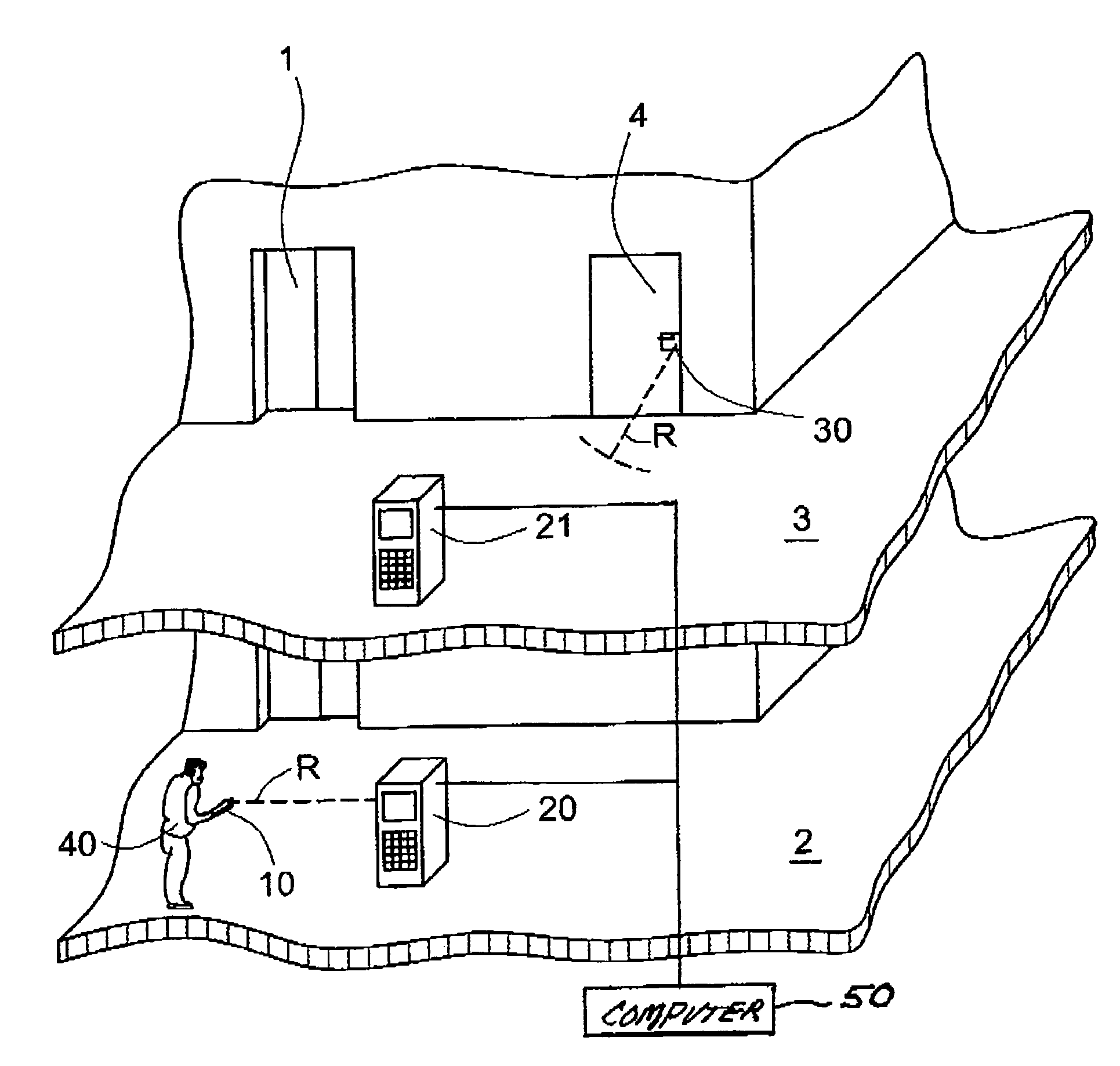
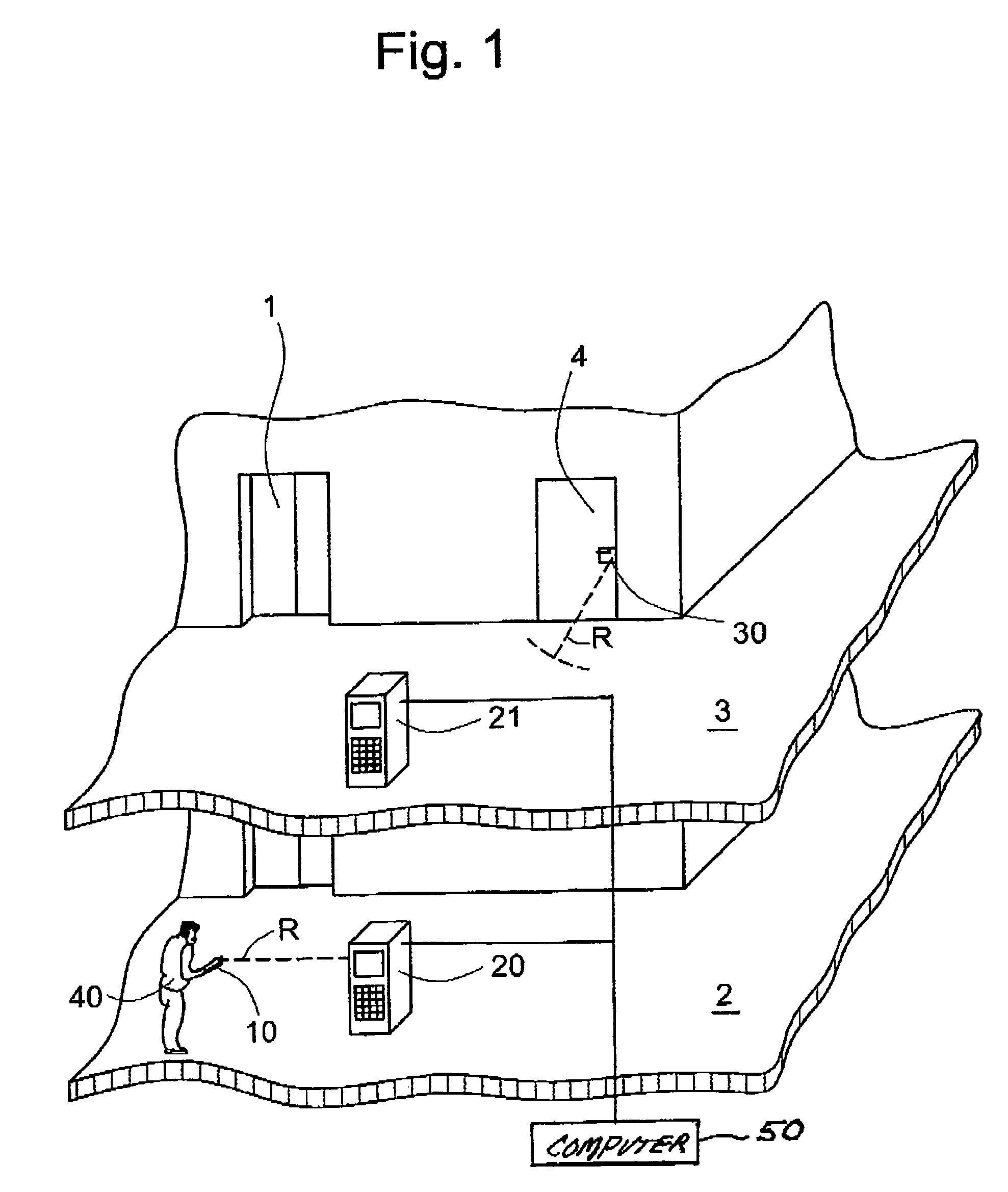
[0028]FIG. 1 shows schematically a detail of a building with a system for the exchange of data, wherein the system additionally serves for guidance of a user 40 in the building and for access control to an elevator 1 and to a room closed by a door 4. The system provides the elevator 1 by which the user 40 can be transported from a first floor 2 to a second floor 3. In addition, a first terminal 20 is disposed in the vicinity of the elevator 1 in the first floor 2 and a second terminal 21 is disposed in the vicinity of the elevator 1 in the second floor 3. Terminals 20 and 21 respectively form a first communications unit and are connected with a computer unit 50. In order to grant access to the elevator 1 as well as to the room closed by the door 4 the user 40 carries a mobile telephone 10 which forms a mobile communications unit. The door 4 is equipped with a transmitter / receiver unit 30 that forms a second communications unit. The mobile telephone 10 has a memory unit, an interface...


PUM


Abstract

A method for exchange of data between a mobile communications unit carried by a user and at least one of a first communications unit, a second communications unit and a computer unit positioned at different locations in an environment such as a building. When the first communications unit and the mobile communications unit are spaced at a predetermined distance, a near-field radio connection is generated within this distance. After data exchange between the mobile communications unit and the first communications unit, the data are communicated by the first communications unit to the computer unit. When the second communications unit and the mobile communications unit are spaced from one another at the predetermined distance, a near-field radio connection is generated within this distance. A data exchange takes place between the mobile communications unit and the second communications unit by the near-field radio connection.

Description

BACKGROUND OF THE INVENTION[0001]The invention relates to a method for the exchange of data between a mobile communications unit carried by a user and at least one first communications unit, a second communications unit and a computer unit.[0002]Electronic door locks are used in modern hotel complexes for access to the rooms. For reasons of cost these electronic door locks are not wired and are operated with batteries for energy supply. Two methods are known for distribution of locked access codes to all electronic door locks and for collation of data from all electronic door locks, for example battery charge state and who has access when.[0003]In a first method all door locks are equipped with infrared interfaces. However, the disadvantage exists with systems of that kind in that data collectors with infrared interfaces, which exchange the data with the door locks, have to be installed in the hotel corridors at the ceilings at various locations. On the other hand, the data collecto...

Claims


Application Information

Patent Timeline
Patent Type & Authority Patents(United States)
IPC IPC(8): H04B7/00G06F21/31G06F21/33G06F21/34
CPCG07C9/00309G07C2009/00793G07C2011/02G07C2209/63
Inventor GERSTENKORN, BERNHARD
Owner INVENTIO AG
Why Eureka
Try Eureka