
Air Cooler for Supercharged Combustion Engine

a supercharged combustion engine and air cooler technology, applied in the field of air coolers, can solve the problems of water vapour in the air, air coolers may condense and freeze to become ice, and flow paths may to a greater or lesser extent be blocked, so as to achieve good heat-conducting characteristics, good heat-conducting characteristics, and excellent heat-conducting characteristics

Inactive Publication Date: 2007-11-01
SCANIA CV AB
View PDF13 Cites 2 Cited by
  • Summary
  • Abstract
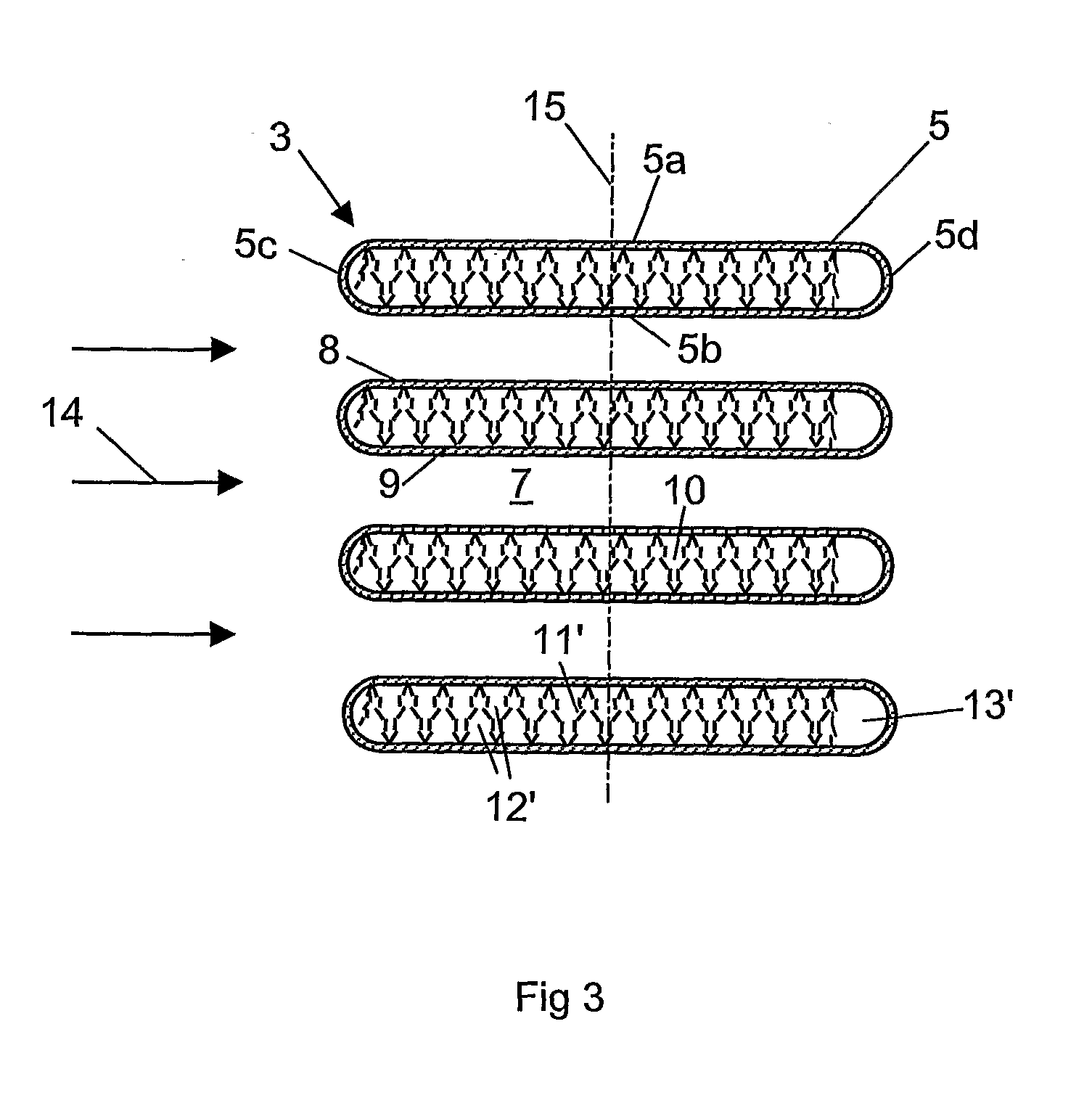
  • Description
  • Claims
  • Application Information

AI Technical Summary

Benefits of technology

[0008] According to an embodiment of the present invention, said elongate duct is arranged at a front side of the tubular portion with respect to the direction of flow of the medium. At the front side, the medium will initially flow in contact with a surface of the tubular portion. This is where the medium is at its lowest temperature. The most effective cooling of the tubular element thus takes place at said front side. Such a location of the elongate duct is often sufficient to provide the air in the duct with fully acceptable cooling without the assistance of a heat transfer element. According to another embodiment, the elongate duct may alternatively be arranged at a rear side of the tubular portion with respect to the direction of flow of the medium. Since the temperature of the medium rises as it flows past the heat transfer element, there is less cooling action at the rear side of the heat transfer element. There is thus less risk of ice formation in the elongate duct. The elongate duct may therefore be of a smaller size. It is also possible to arrange the duct in an intermediate portion of the passage with heat transfer elements fitted on mutually opposite sides.
[0009] According to another preferred embodiment of the present invention, said passage has a cross-sectional profile with a greater extent in the direction of flow of the medium than in a direction perpendicular to said direction of flow. Such a configuration of the tubular element results in a relatively elongate contact surface with respect to the flowing medium, thereby promoting cooling of the air in the tubular element. With advantage, said elongate duct has a cross-sectional profile with substantially the same width as height. If for example the duct has a cross-sectional profile of underdimensioned extent in height or width, there is obvious risk that ice may build up in the direction of underdimensioned extent of the duct in such a way as to block the duct. If on the contrary the duct is of overdimensioned extent in one direction, the result is an unnecessarily tall or wide duct. Such an overdimensioned duct reduces the number of flow paths, leading to less cooling of the air passing through the tubular element. An optimum duct is therefore likely to be of substantially same extent in height and width.
[0011] According to a preferred embodiment of the present invention, the tubular element is made of a material which has good heat-conducting characteristics. The result is effective heat transfer between the medium outside and the air inside the tubular element. The tubular element may be made of aluminium, which has excellent heat-conducting characteristics. The heat-conducting element is preferably likewise made of a material which has good heat-conducting characteristics. Here again, aluminium is a suitable material. The heat-conducting element may be made of folded sheet material. Sheet material provides a contact surface which can easily be shaped so that suitable flow paths can be formed in the passage. The contact surfaces may be shaped in such a way as to promote turbulent flow through the flow paths. The surfaces may for example have a gill-like structure, resulting in still more effective cooling of the air in the tubular element.
[0012] According to a preferred embodiment of the present invention, the air cooler is a charge air cooler adapted to cooling air which is at above atmospheric pressure. A charge air cooler may be used inter alia in a vehicle to cool compressed air before it is led to a supercharged combustion engine. It is not uncommon for the compressed air to be cooled in the charge air cooler to a temperature below the dewpoint temperature, with the result that water vapour in the air condenses inside the charge air cooler. Conventional charge air coolers are usually cooled by surrounding air. If the surrounding air is at a very low temperature, there is also risk that condensate inside the charge air cooler may freeze to become ice. The elongate duct according to the invention in the charge air cooler's tubular element makes it possible in substantially all circumstances to maintain sufficient air flow through the charge air cooler for running the supercharged combustion engine.

Problems solved by technology

When the medium, which may be surrounding air, is at a very low temperature, there is risk that water vapour in the air which is to be cooled in the air cooler may condense and freeze to become ice.
As the heat transfer element divides the passage into relatively narrow flow paths, there is obvious risk that the flow paths may to a greater or lesser extent be blocked if ice forms on surfaces of the heat transfer element.
If for example the duct has a cross-sectional profile of underdimensioned extent in height or width, there is obvious risk that ice may build up in the direction of underdimensioned extent of the duct in such a way as to block the duct.
If on the contrary the duct is of overdimensioned extent in one direction, the result is an unnecessarily tall or wide duct.

Method used


Image

  • Air Cooler for Supercharged Combustion Engine
  • Air Cooler for Supercharged Combustion Engine
  • Air Cooler for Supercharged Combustion Engine

Examples


Embodiment Construction

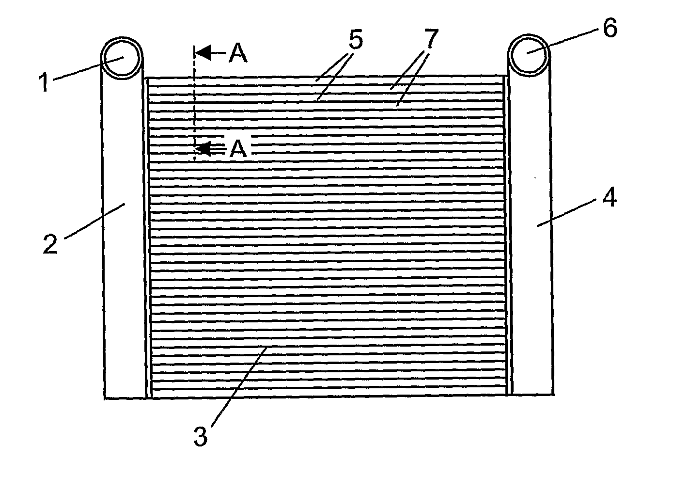
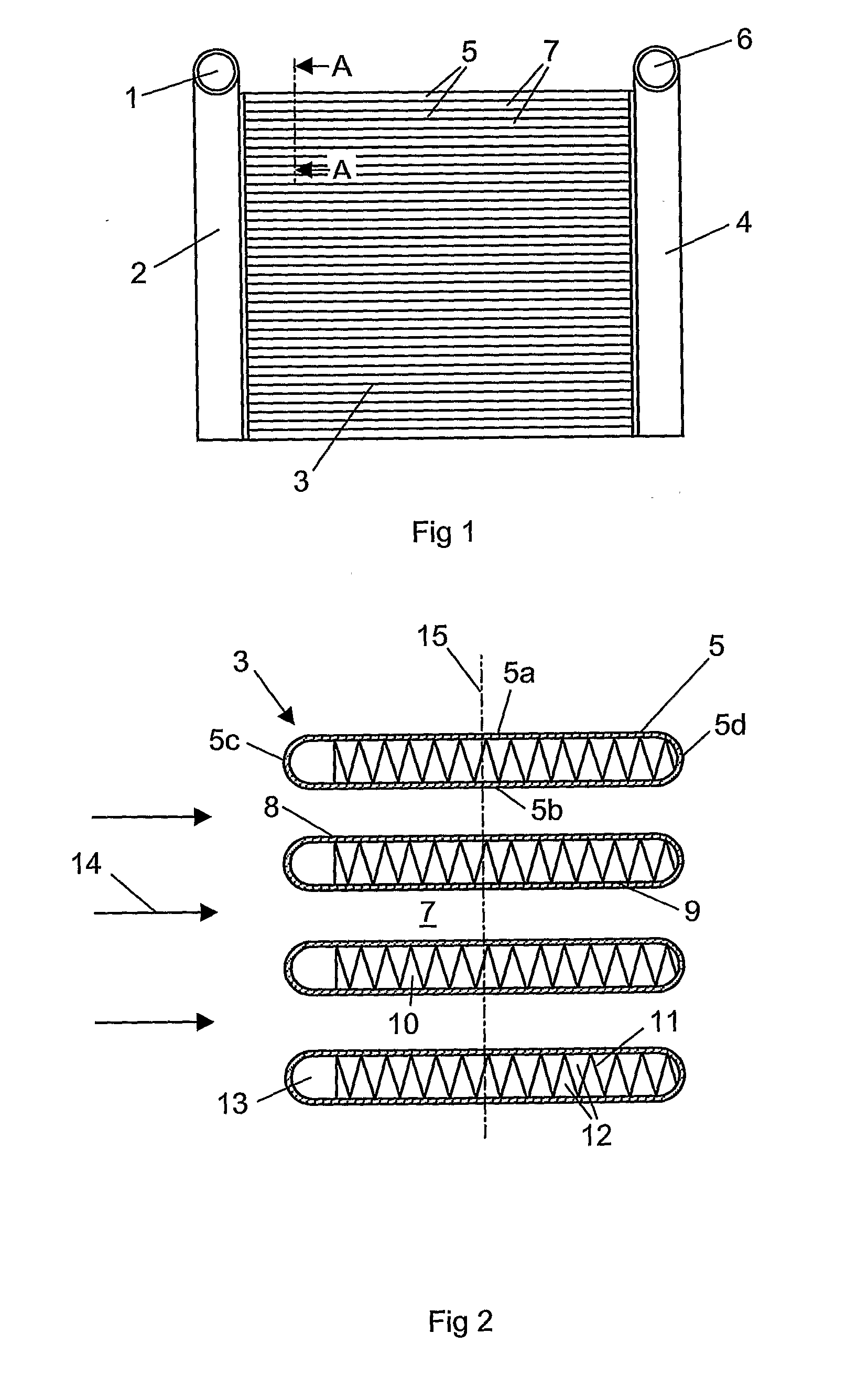
[0017]FIG. 1 depicts a charge air cooler which may for example be fitted at a front portion of a vehicle which is powered by a supercharged combustion engine. A supercharged combustion engine needs a supply of compressed air. The function of the charge air cooler is to cool the compressed air before it is led to the combustion engine. The charge air cooler comprises an inlet 1 to a first gathering tank 2 for receiving warm compressed air from a compressor. The first gathering tank 2 comprises a plurality of internal apertures via which the compressed air can be led to a cooler package 3 which extends between the first gathering tank 2 and a second gathering tank 4. The cooler package 3 comprises a plurality of tubular elements 5 which extend in a substantially rectilinear manner between the first gathering tank 2 and the second gathering tank 4. The tubular elements 5 are arranged parallel vertically above one another. The tubular elements 5 are arranged at a substantially uniform d...


PUM


Abstract

An air cooler comprises at least one tubular element with an inside surface which defines a passage for air which is to be cooled in the air cooler. At least one heat-conducting element is fastened inside the passage and is shaped to divide the passage into a plurality of flow paths between the inlet and the outlet of the passage. A medium at a lower temperature than the air to be cooled in the air cooler flows in contact with an outside surface of the tubular element cooling the air in the air cooler as the air is led through the passage. The heat-conducting element is sized such that it occupies only part of the cross-section of the passage in the direction of flow of the medium, thereby forming in a remaining portion of the passage in the direction of flow of the medium an elongate duct between the inlet and the outlet of the passage. The duct has a larger cross-sectional area than the cross-sectional areas of the respective flow paths between the inlet and the outlet of the passage which are formed by the heat-conducting element.

Description

BACKGROUND TO THE INVENTION, AND STATE OF THE ART [0001] The present invention relates to an air cooler according to the preamble of claim 1. [0002] The amount of air which can be supplied to a supercharged combustion engine of a vehicle depends on the pressure of the air but also on the temperature of the air. Supplying the largest possible amount of air to a supercharged combustion engine entails cooling compressed air in a charge air cooler before it is led to the combustion engine. The charge air cooler is usually situated in front of the conventional radiator of a vehicle. A charge air cooler usually comprises two gathering tanks and a plurality of tubular elements arranged in parallel which connect the gathering tanks. The parallel tubular elements are arranged at a distance from one another so that surrounding cold air can flow between the tubular elements and cool the compressed air in the tubular elements. The compressed air can be cooled to a temperature substantially corr...

Claims


Application Information

Patent Timeline
Patent Type & Authority Applications(United States)
IPC IPC(8): F25D23/00
CPCF02B29/0456F28D1/05366F28F19/006F28F1/40Y02T10/146F28D2021/0082Y02T10/12F28F3/025
Inventor PETTERSSON, RICKARD
Owner SCANIA CV AB
Learn More