
Energy router for energy internet

a router and energy internet technology, applied in the direction of electric variable regulation, process and machine control, instruments, etc., can solve the problems of large energy flow limit, single energy conversion form, and stability and reliability of traditional large-scale centralized power supply, and achieve small no-load loss, small volume, and light weight

Inactive Publication Date: 2017-02-07
NORTHEASTERN UNIV
View PDF3 Cites 2 Cited by
  • Summary
  • Abstract
  • Description
  • Claims
  • Application Information

AI Technical Summary

Benefits of technology

The present invention provides an energy router for the energy internet that can supply plug and play electric energy, with functions of converting voltage, transferring energy, limiting fault current, compensating reactive power, improving quality of electric energy, and providing standardized interfaces for various devices. Compared with traditional transformers, the energy router has the advantages of smaller volume, light weight, no-load loss, and no use of insulating oil. Compared with traditional single-phase rectification solid state transformers, the energy router has larger capacity and outputs less electric energy harmonic. A six-phase interleaved DC / DC conversion unit is adopted for high-frequency operation, reducing the size of the transformer in the circuit. The energy router has multiple voltage levels to meet the demands of various loads and energy storage devices. The patent multi-unit topological structure provides bi-directional flow of energy and can provide electric energy with multiple voltage levels.

Problems solved by technology

With the rapid increase in power load, the problem about stability and reliability of the traditional large-scale centralized power supply has occurred.
The existing power conversion device with a solid state transformer as the core has small power capacity, single level of voltage it can supply, large limit on energy flow, single energy conversion form and low efficiency due to its backward topological structure.

Method used


Image

  • Energy router for energy internet
  • Energy router for energy internet
  • Energy router for energy internet

Examples


Embodiment Construction

[0051]One embodiment of the present invention is detailed in combination with the figures.

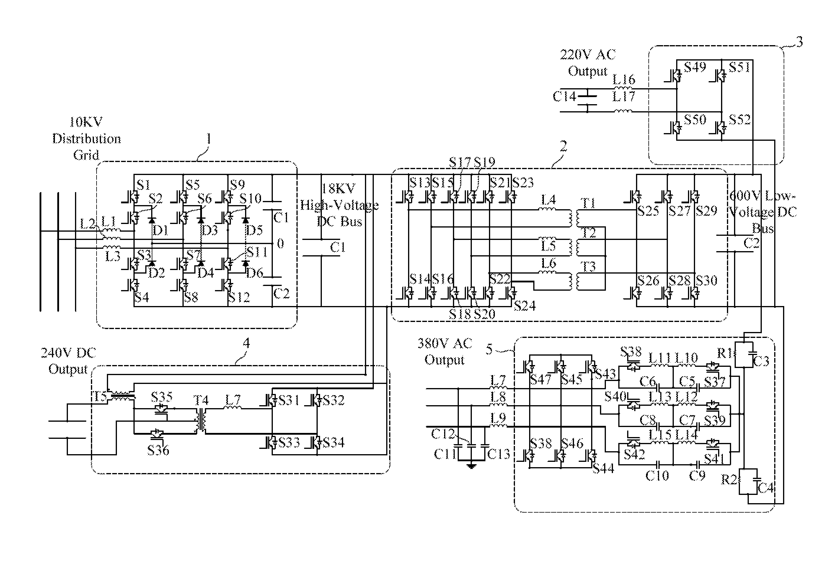
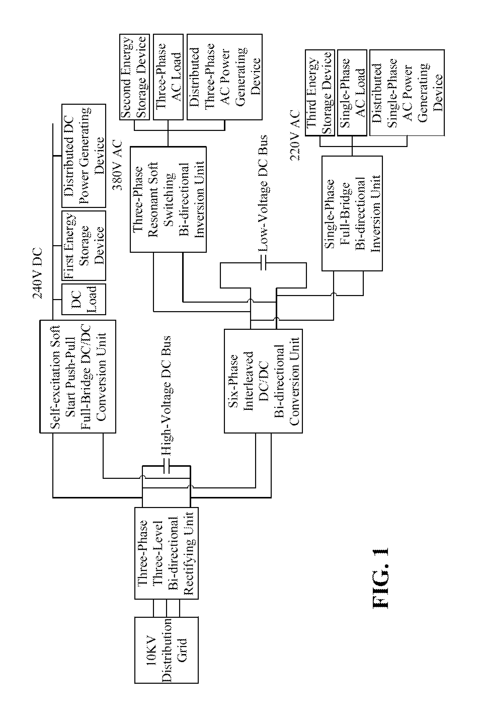
[0052]An energy router for an energy internet, as shown in FIG. 1, comprises a three-phase three-level bi-directional rectifying unit, a six-phase interleaved DC / DC bi-directional conversion unit, a self-excitation soft start push-pull full-bridge DC / DC bi-directional conversion unit, a three-phase resonant soft switching bi-directional inversion unit, a single-phase full-bridge bi-directional inversion unit, a high-voltage DC bus and a low-voltage DC bus.

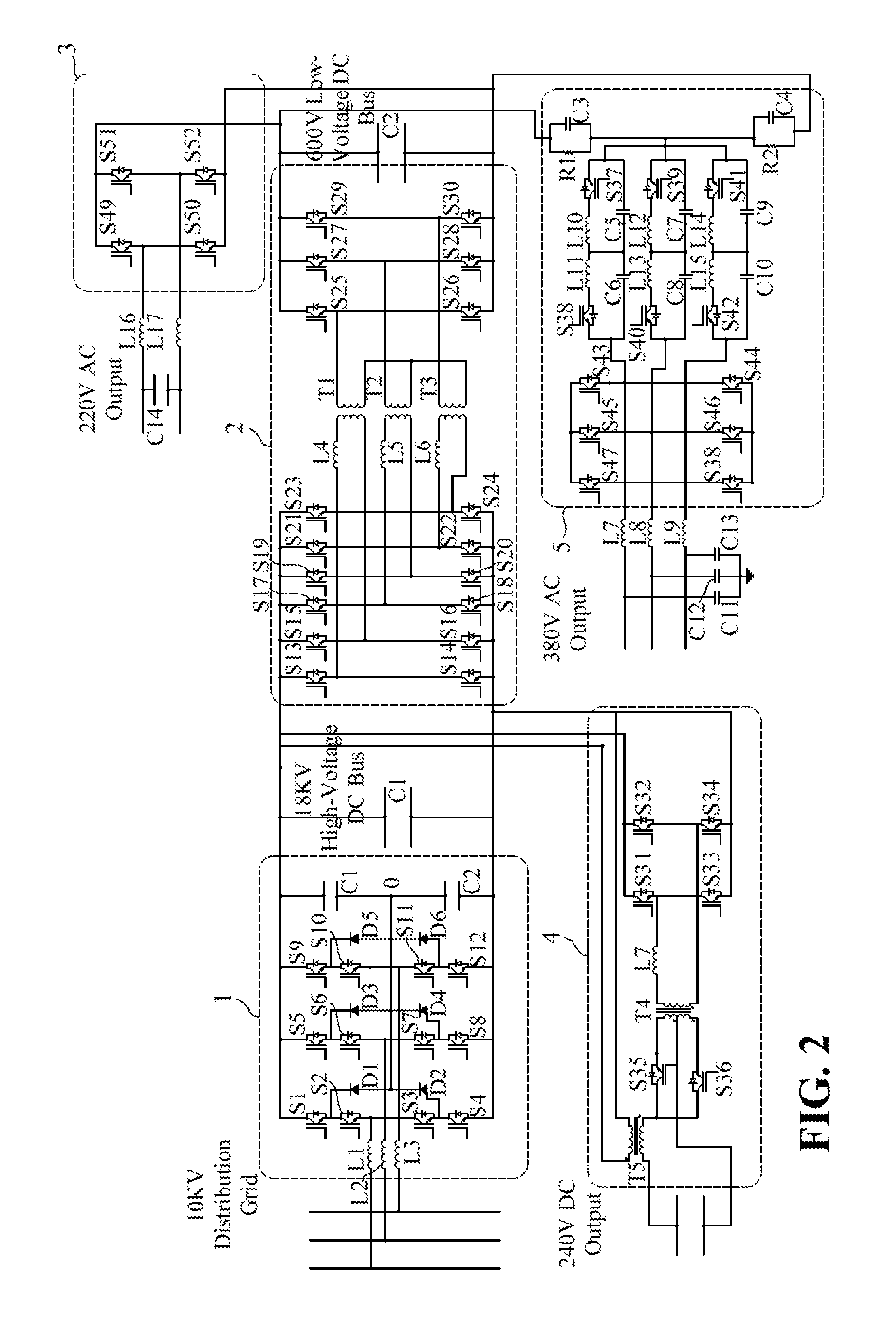
[0053]The high-voltage DC bus has adjustable high-voltage direct current, and the voltage of the high-voltage DC bus in the embodiment is about 18 KV.

[0054]The low-voltage DC bus has adjustable low-voltage direct current with the voltage of 600V to 800V, and the voltage of the low-voltage DC bus in the embodiment is 600V.

[0055]The schematic circuit diagram of the energy router for the energy internet is shown in FIG. 2. The input end of the th...


PUM


Abstract

The present invention relates to an energy router for an energy internet, which comprises a three-phase three-level bi-directional rectifying unit, a six-phase interleaved DC / DC bi-directional conversion unit, a self-excitation soft start push-pull full-bridge DC / DC bi-directional conversion unit, a three-phase resonant soft switching bi-directional inversion unit, a single-phase full-bridge bi-directional inversion unit, a high-voltage DC bus and a low-voltage DC bus. The three-phase three-level bi-directional rectifying unit, the six-phase interleaved DC / DC bi-directional conversion unit, the self-excitation soft start push-pull full-bridge DC / DC bi-directional conversion unit, the three-phase resonant soft switching bi-directional inversion unit and the single-phase full-bridge bi-directional inversion unit each have three energy flow operating modes: a forward conduction, a reverse conduction and a non-conduction. According to the energy flow operating mode of each unit, different operating modes of the energy router for the energy internet are formed.

Description

CROSS-REFERENCE TO RELATED APPLICATION[0001]This application claims the priority of Chinese patent application No. 201510082066.4, filed on Feb. 16, 2015, which is incorporated herewith by reference.BACKGROUND OF THE INVENTION[0002]1. Field of the Invention[0003]The present invention belongs to the technical field of electric and electronic power conversion, in particular relates to an energy router for an energy internet.[0004]2. The Prior Arts[0005]From the 20th century, with the development of economy and society, energy is consumed increasingly, so people is forced by rapid increase in power demand to pay more attention to development of renewable energy. With the rapid increase in power load, the problem about stability and reliability of the traditional large-scale centralized power supply has occurred. Every country turns its attention on research on development of electric energy to use of clean renewable energy and distributed energy, and the distributed power generating sy...

Claims


Application Information

Patent Timeline
Patent Type & Authority Patents(United States)
IPC IPC(8): H02J1/00H02M7/797H02M7/219H02M3/337H02M3/28H02J5/00H02M1/00
CPCH02J1/00H02J5/00H02M3/285H02M3/337H02M7/219H02M7/797H02M2001/007H02J4/00H02M3/1582H02J1/14Y02B70/10H02M1/007H02M3/33573H02M3/01
Inventor SUN, QIUYEZHANG, HUAGUANGMA, DAZHONGHUANG, BONANCHEN, LEIDU, HENGLIU, ZHENWEITENG, FEIHUI, GUOTAO
Owner NORTHEASTERN UNIV
Learn More