Retention device for medical components

a technology for retaining devices and medical components, which is applied in the direction of tube connectors, feeding tubes, other medical devices, etc., can solve the problems of difficult separation of components when desired, inability to readily accommodate such a variety of differently shaped connectors, and insufficient force to create, so as to improve the retention of connectors within the adapter.

Active Publication Date: 2010-02-23
AVENT INC
View PDF59 Cites 34 Cited by
  • Summary
  • Abstract
  • Description
  • Claims
  • Application Information

AI Technical Summary

Benefits of technology

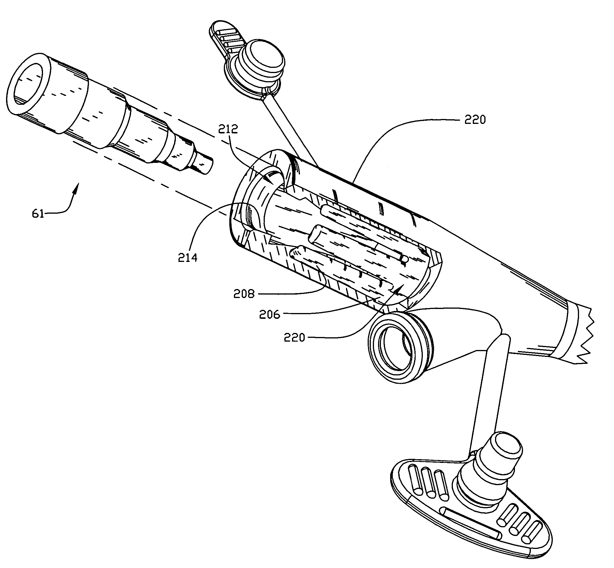
[0016]The present invention also contemplates an aspect which is directed to an adapter adapted for use with a tube, the adapter including a skeleton and a shell. The skeleton includes a first end, an inner surface, an outer surface, and a plurality of fingers extending opposite the first end, the fingers of the adapter being flexible. The shell contacts at least a portion of the outer surface of the skeleton. The skeleton is adapted to be received by or within the tube and is adapted to flex so that upon sufficient insertion of a connector the adapter contacts the connector in such a manner as to create an interface between the adapter and the connector and upon removal of the connector the fingers adopt a shape at least substantially the same as that prior to insertion of the connector. The skeleton is generally configured to urge the contours of the shell to interface with the connector when present so as to enhance retention of the connector within the adapter.

Problems solved by technology

Unfortunately, such earlier inlet ports often could not readily accommodate such a variety of differently shaped connectors without the need to forcibly insert or forcibly remove the connectors.
Depending on the tube and connector being used this forcing still may not be sufficient to create a connection which retains the connector in the tube so as to avoid an unintentional and / or undesired disconnection.
Further, if sufficient force is applied during the connection of the prior connectors and tubes it may be such that the components are difficult to separate when desired.
Such difficulties in separation may result in displacement of the feeding tube and / or discomfort to the patient during the attempted separation or even after the connector is ultimately separated from the tube.
These problems are only further exacerbated by the fact that it may be desired to use a certain type or brand of feeding device while the feeding bag or feeding set and the connector affixed thereto may be of a different brand and thus may not fit or connect with the feeding device as well as one specifically intended for use therewith.
As a result a less desirable feeding device may be necessary in order to obtain the desired connection with the connector of the selected feeding set or a less desirable feeding solution in a feeding set having a connector which is compatible with the selected feeding device may be required to be selected for compatibility purposes.

Method used


Image

  • Retention device for medical components
  • Retention device for medical components
  • Retention device for medical components

Examples


Embodiment Construction

[0030]The following detailed description will be made in the context of an adapter which is adapted for medical use. It is readily apparent, however, that the adapter would also be suitable for use with other types of systems, circuits or conduits and the like and is not intended to be limited to medical devices or use in a medical field. In addition, the invention will be described in the context of its various configurations. It should be appreciated that alternative arrangements of the invention can comprise any combination of such configurations. As such, the use of a desired aspect for ease in understanding and describing the invention shall not, in any manner, limit the scope of the invention.

[0031]Reference will now be made to the drawings in which the various elements of the present invention will be given numeral designations and in which the invention will be discussed so as to enable one skilled in the art to make and use the invention. It should be appreciated that each ...


PUM


Abstract

The present invention is directed generally to an adapter for assist with the connection of a flexible tubing to a connector, and more particularly to a product that enables the flexible tubing to retain its ability to provide a secure connection even after multiple uses by resisting or limiting permanent deformation thereof.

Description

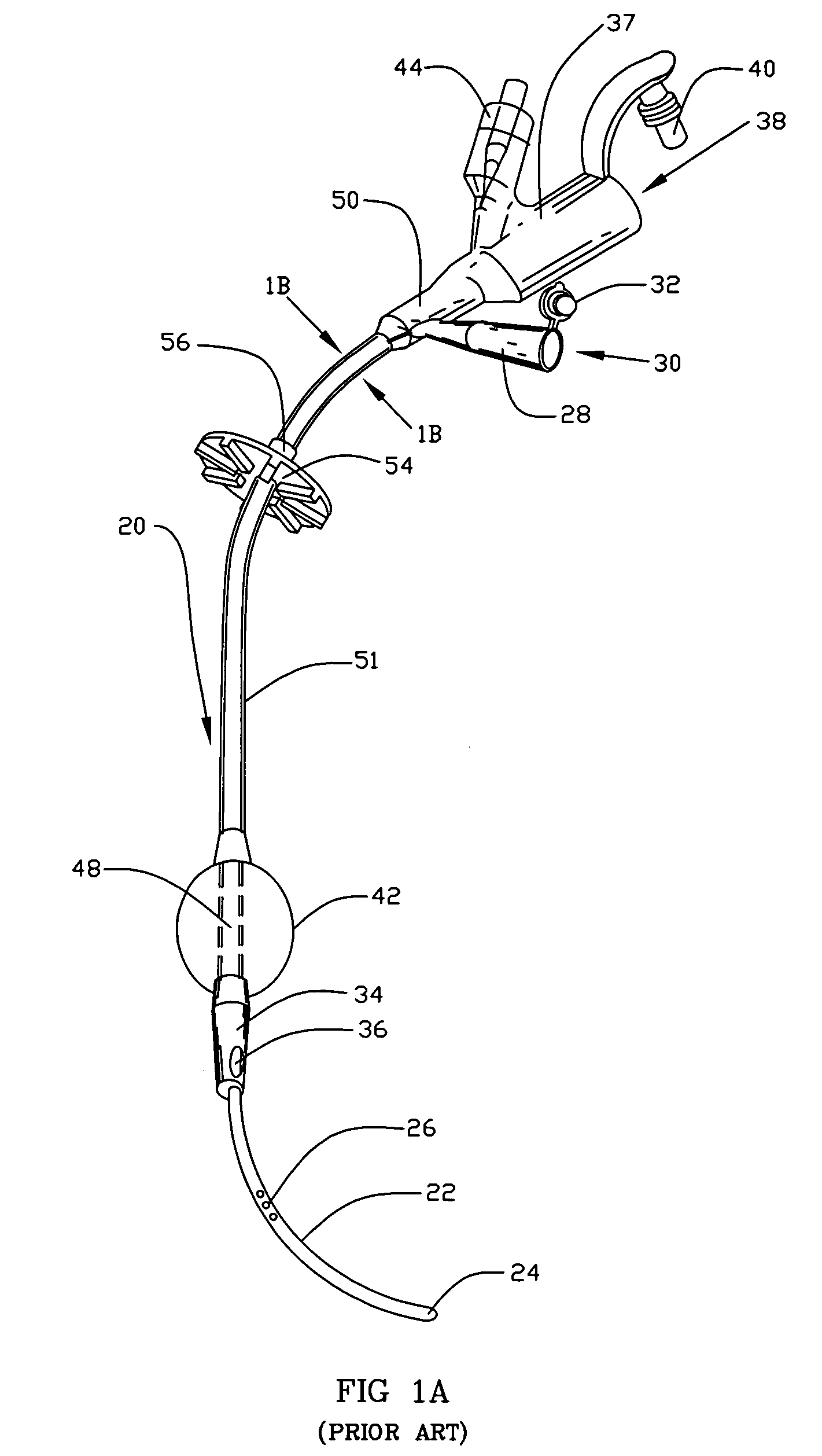
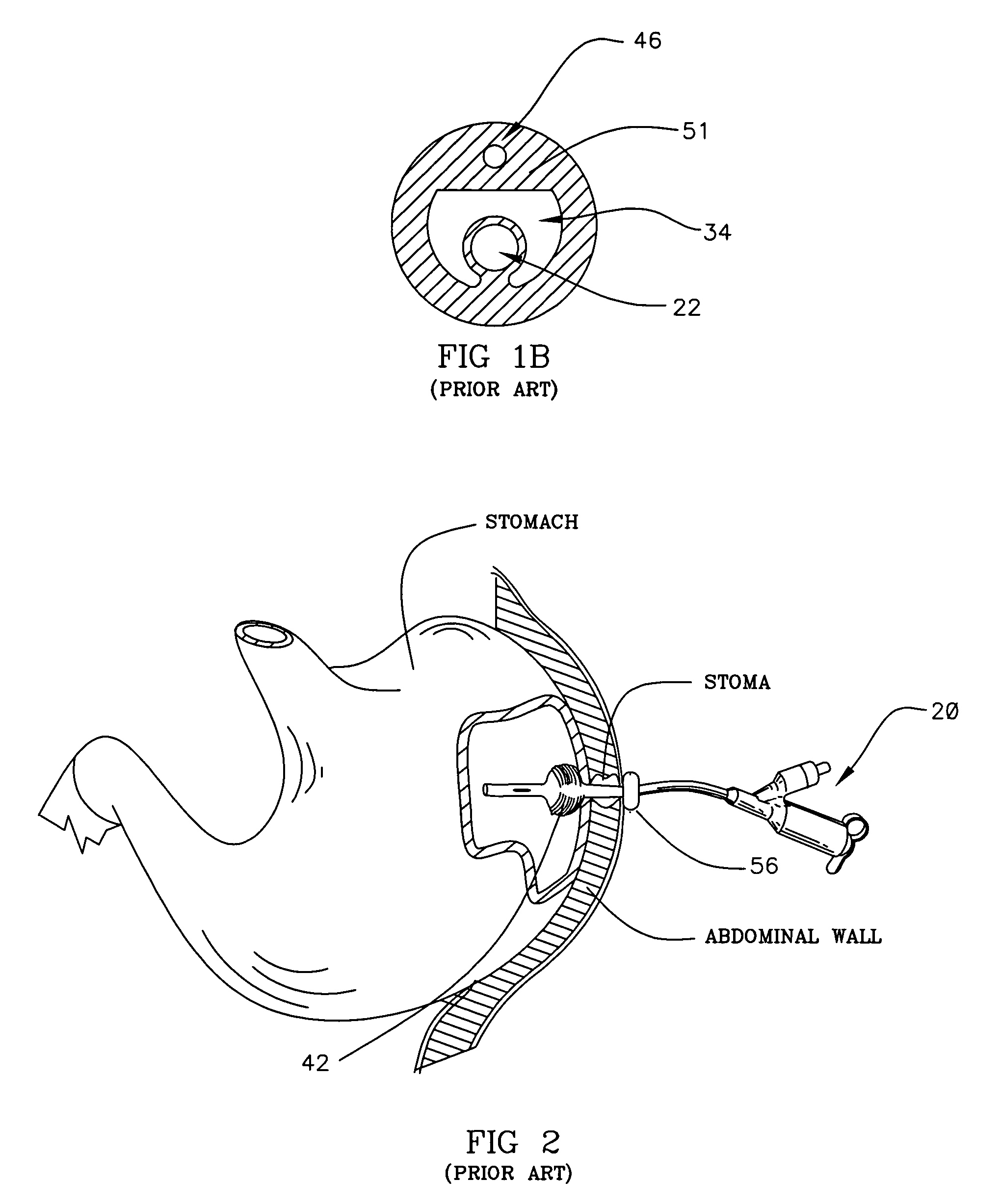
BACKGROUND OF THE INVENTION[0001]Enteral tubes for providing food and medication to a patient are well known. For example, U.S. Pat. No. 4,666,433, entitled Gastrostomy Feeding Device, invented by Parks and issued May 19, 1987; U.S. Pat. No. 4,701,163, entitled Gastrostomy Feeding Device, invented by Parks and issued Oct. 20, 1987; U.S. Pat. No. 4,798,592, entitled Gastrostomy Feeding Device, invented by Parks and issued Jan. 17, 1989; and U.S. Pat. No. 4,685,901, entitled Gastro-Jejunal Feeding Device, invented by Parks and issued Aug. 11, 1987 disclose earlier feeding tubes.[0002]Referring to the illustrative drawing of FIG. 1A, there is shown a perspective view of an earlier enteral feeding device 20. The device 20 includes an elongated tubular member 51 formed from a stretchable elastomeric material such as silicone. FIG. 1B is an illustrative cross-sectional view of the tubular member 51 of the earlier device. The tubular member 51 defines a jejunal tube 22, a gastronomy tube 3...

Claims


Application Information

Patent Timeline
Patent Type & Authority Patents(United States)
IPC IPC(8): A61M25/00A61J15/00A61M39/10
CPCA61M39/10A61M2039/1027A61M2039/1077
Inventor MCMICHAEL, DONALD J.
Owner AVENT INC
Why Eureka
Try Eureka