
Connector for securing wiper blade to wiper arm and wiper blade assembly

a technology for securing wiper blades and wiper arms, which is applied in the direction of vehicle maintenance, vehicle cleaning, domestic applications, etc., can solve the problems of difficult hand-operated operation, insufficient detachment of the connector, and operator's inability to check the connection by sight, etc., to achieve easy attachment of the locking member, reduce cost, and simple structure

Inactive Publication Date: 2010-03-02
DENSO WIPER SYST INC
View PDF17 Cites 8 Cited by
  • Summary
  • Abstract
  • Description
  • Claims
  • Application Information

AI Technical Summary

Benefits of technology

"The present invention provides a connector for securing a wiper blade to a wiper arm, which includes a base member, a locking member, and a flexible connecting member. The base member is attached to the wiper blade, the locking member is operatively associated with the base member, and the flexible connecting member connects the base member with the locking member. The connector allows for easy attachment to the wiper arm and reduces vibrations between the wiper blade and the wiper arm. The connector can be designed to move between a position for connecting the wiper blade with the hook portion of the wiper arm and a position for connecting the wiper blade with the side pin of the wiper arm. The connector includes a joint portion that receives a pivot pin of the wiper blade, and the wiper blade includes an opening for receiving the side pin. The connector and wiper blade assembly provide a simple structure for securely attaching a wiper blade to a wiper arm."

Problems solved by technology

Thus, the connector 100 cannot sufficiently prevent detaching of the side pin 11 from the wiper blade.
Thus, an operator cannot check the connecting by sight.
Also, such an operation is hard work to carry out by hand since the space under the connector 100 is not enough large to put the fingers of the operator into there.

Method used


Image

  • Connector for securing wiper blade to wiper arm and wiper blade assembly
  • Connector for securing wiper blade to wiper arm and wiper blade assembly
  • Connector for securing wiper blade to wiper arm and wiper blade assembly

Examples


Embodiment Construction

[0048]Hereinafter, with reference to the accompanying drawings, an embodiment of the present invention will be described.

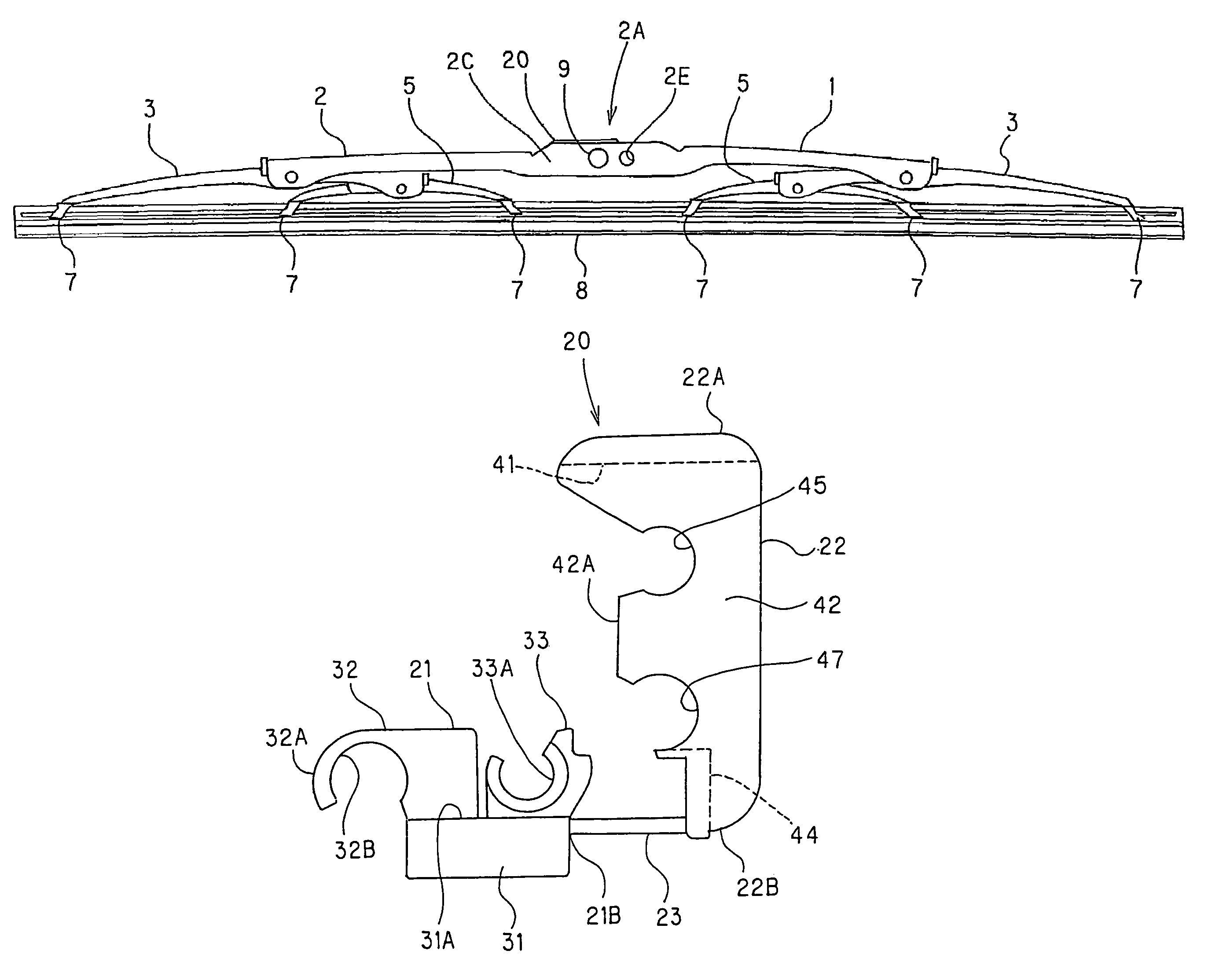
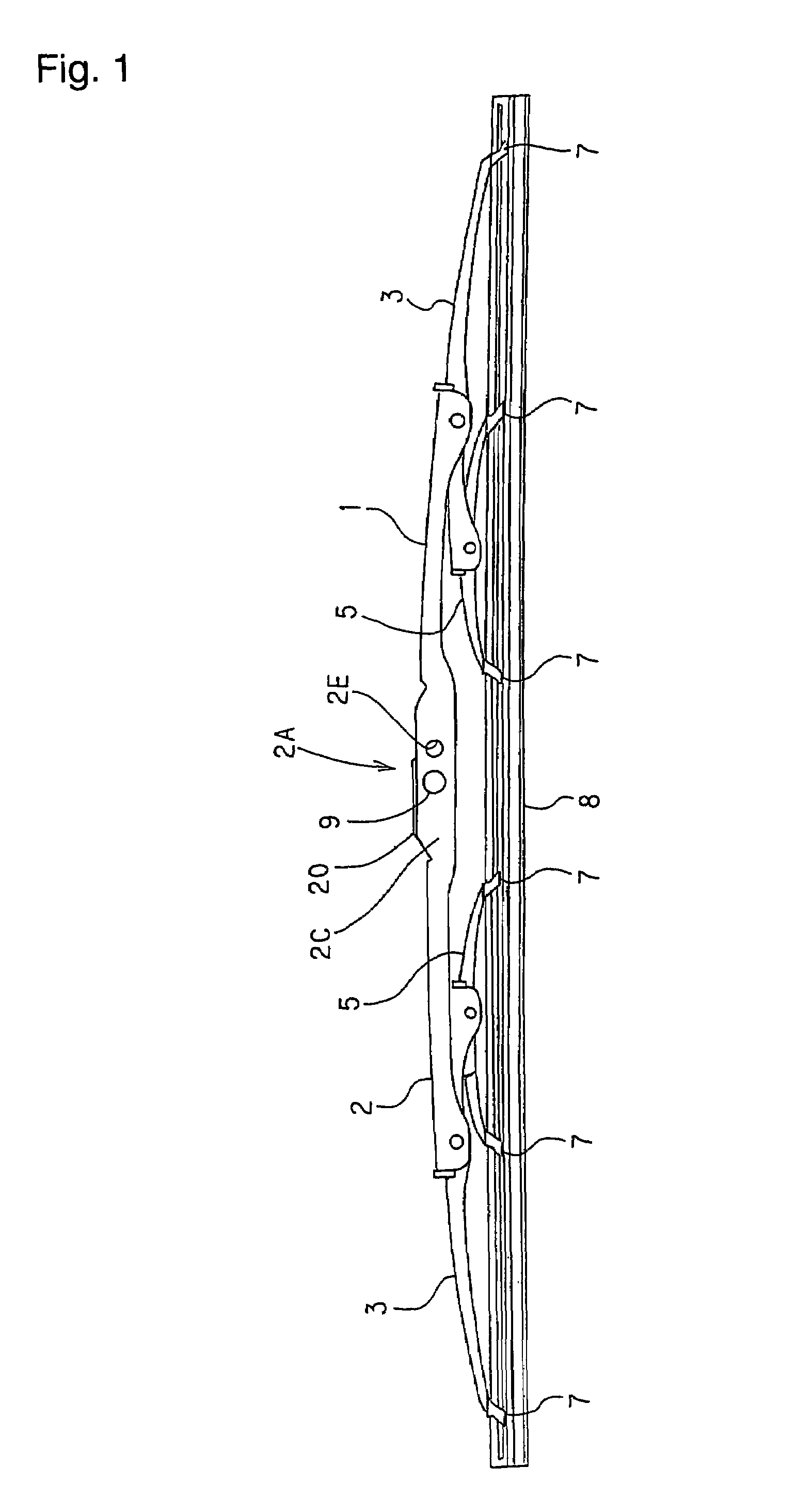
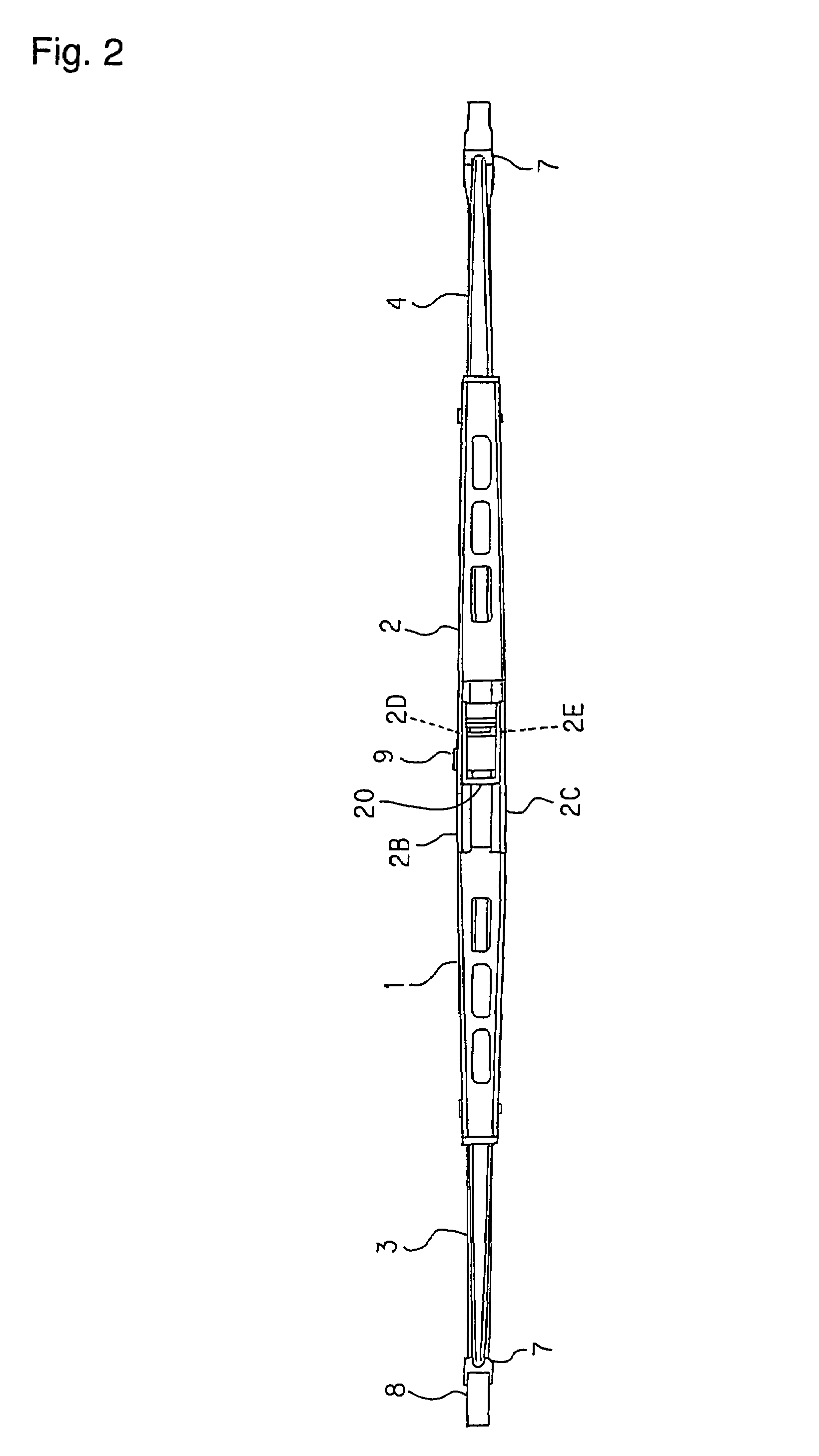
[0049]FIGS. 1 and 2 show the overall structure of a wiper blade assembly. The wiper blade assembly includes the wiper blade 1 and a connector 20 for securing the wiper blade 1 to the wiper arm 10 (See FIG. 6).

[0050]The wiper blade 1 includes a primary lever 2. Secondary levers 3 and 4 are rotatably supported at the both ends of the primary lever 2. Yoke levers 5 and 6 are rotatably supported at the inside ends of the secondary levers 3 and 4. Supporting claws 7 are disposed at the outside ends of the secondary levers 3 and 4 and the both ends of the yoke levers 5 and 6. A wiper rubber 8 is supported by the supporting claw 7.

[0051]The primary lever 2 includes side plates 2B and 2C. An opening 2A is formed between the side plates 2B and 2C and is disposed at the substantially central portion of the primary lever 2. A pivot pin 9 is disposed at a substantially centra...


PUM


Abstract

A connector (20) for securing a wiper blade to a wiper arm includes a base member (21) including a forward upper portion (32) and a rearward upper portion (33); a locking member (22) for holding either a U-hook portion (12) or a side pin (11) mounted to the base member (21); and a flexible connecting member (23) connecting the locking member (22) to the base member (21). To attach the connector (20) to the side pin (11), the connector is rotated toward the side pin (11) from the opposite side of the side pin (11) so that the side pin (11) fits into a recess (33A) of the rearward upper portion (33). The side pin (11) also fits into the recesses (47 and 48) of the locking member (22) so that the side pin (11) is held between the base member (21) and the locking member (22). The connector enables the firm securing of the wiper blade to the wiper arm so as to restrict vibrations between the wiper blade and the wiper arm.

Description

TECHNICAL FIELD[0001]The present invention relates to a connector used in a wiper device for securing a wiper blade to a wiper arm.BACKGROUND ART[0002]A wiper device is generally comprised of a wiper blade, a wiper arm and a driving motor. The wiper blade includes a wiper rubber which wipes a surface to be wiped, such as an automobile windshield. The wiper blade is connected with the wiper arm which is associated with a driving motor, for example, through a linking member. The driving motor drives the wiper blade through the wiper arm so that the wiper rubber wipes the surface.[0003]FIG. 12(C) shows a wiper arm 10′ used in a wiper device. The wiper arm 10′ includes a U-shaped tip portion (U-hook portion 12) which is designed to be connected with the wiper blade via a connector (hook-type securing).[0004]FIGS. 12 (A) and (B) show a wiper arm 10 of a different type of securing. The wiper arm 10 includes a side pin 11 adjacent to its tip portion. The side pin 11 fits into an opening fo...

Claims


Application Information

Patent Timeline
Patent Type & Authority Patents(United States)
IPC IPC(8): B60S1/40
CPCB60S1/40B60S1/4074B60S1/4003B60S1/4009
Inventor INOUE, YUUSUKE
Owner DENSO WIPER SYST INC
Learn More