Shackle structure for suspension leaf spring

a technology of leaf springs and chains, which is applied in the direction of springs/dampers, mechanical devices, transportation and packaging, etc., can solve the problems and achieve the effect of increasing the driveability of the vehicl

Inactive Publication Date: 2010-03-02
NISSAN MOTOR CO LTD
View PDF14 Cites 10 Cited by
  • Summary
  • Abstract
  • Description
  • Claims
  • Application Information

AI Technical Summary

Benefits of technology

[0008]It is, therefore, an object of the present invention to provide a shackle structure for suspension leaf springs capable of increasing driveability of a vehicle during a turning and traveling motion thereof.
[0012]Meanwhile, a rotational momentum occurs on a turning-inner-wheel-side shackle acting as a rebound side. This causes an input load, directed downward, to twist the leaf-spring-side bush support shaft relative to the vehicle-body-side bush support shaft. Accordingly, the turning-inner-wheel-side shackle bears a motion in which the leaf-spring-side component deviates toward the facing the vehicle inside. Therefore, a vehicle axle rotates in a turning direction with a center on the vehicle-body-side front end of the leaf spring, causing both drive wheels to have a toe angle varying under an under-steer condition.
[0013]Accordingly, the drive wheels can be automatically changed to the under-steer state during the turning motion of the vehicle, thereby providing increased driveability of the vehicle during the turning and traveling motion thereof.
[0016]Accordingly, the drive wheels can be automatically changed to the under-steer condition during the turning motion of the vehicle, thereby providing increased driveability of the vehicle during the turning and traveling motion thereof.

Problems solved by technology

This results in a difficulty of increasing driveability of the vehicle with an under-steer characteristic during a turning and traveling motion of the vehicle.

Method used


Image

  • Shackle structure for suspension leaf spring
  • Shackle structure for suspension leaf spring
  • Shackle structure for suspension leaf spring

Examples


first embodiment

[0030]A shackle structure for suspension leaf springs of a first embodiment is shown in FIGS. 1 to 4.

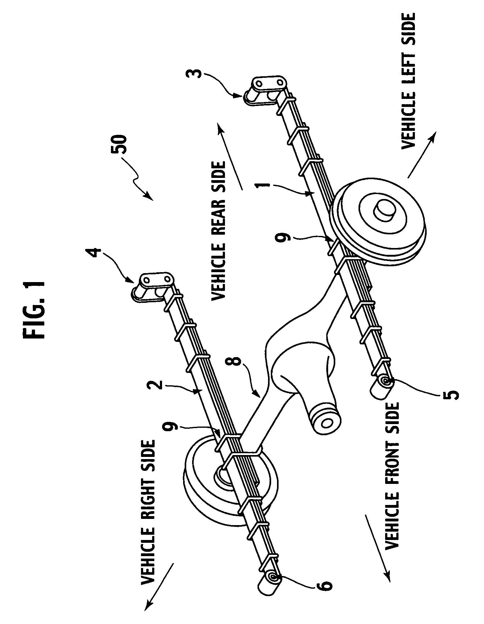
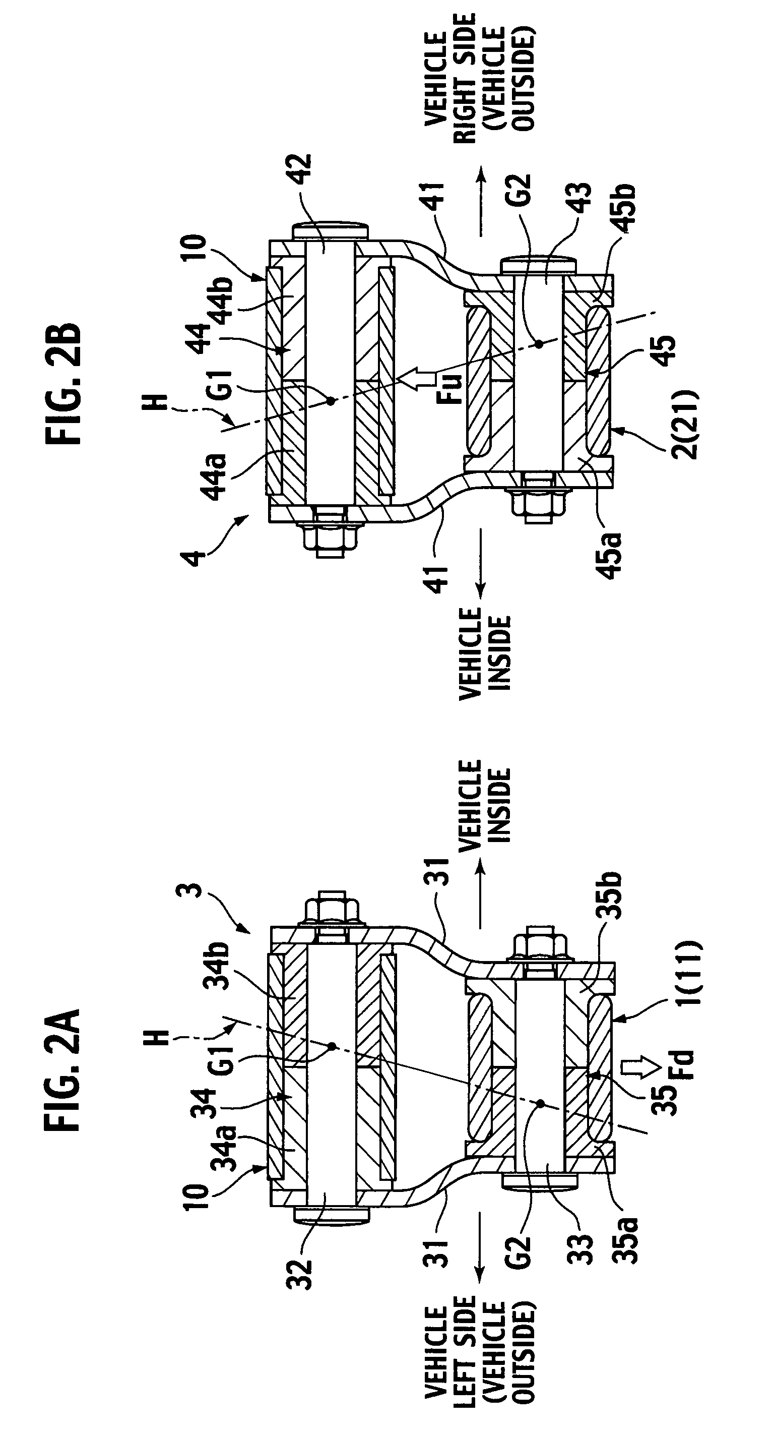
[0031]FIG. 1 is a perspective view showing a vehicular suspension device to which the shackle structure for the suspension leaf springs of the first embodiment is applied. FIGS. 2A and 2B are enlarged cross sectional views showing the shackle structure for the suspension leaf springs of the first embodiment as viewed at a vehicle rear area in a direction toward a vehicle front area. FIGS. 3A and 3B are enlarged cross sectional views showing the shackles appearing in deformed states when a load is applied to the shackles shown in FIGS. 2A and 2B.

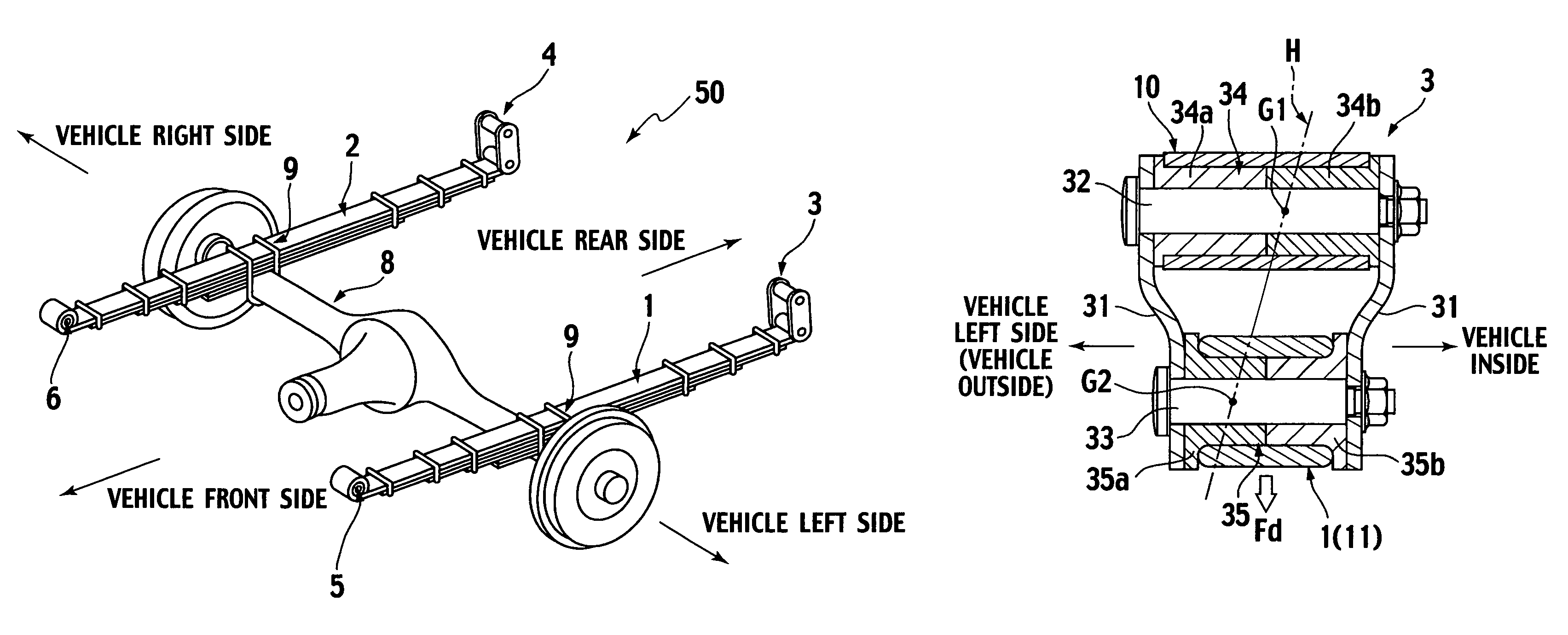
[0032]As shown in FIG. 1, a vehicle suspension device 50, to which the shackle structure for the suspension leaf springs of the first embodiment is applied, includes left and right leaf springs 1, 2, which have vehicle-rear-side end portions mounted on a vehicle body via the shackles 3, 4 and vehicle-front-side end portions mounted on the vehi...

second embodiment

[0071]Next, a second embodiment will be described. The same component parts as those of the first embodiment are omitted from the drawings and bear like reference numerals to omit redundant description. The second embodiment will be described below with a focus on points differing from those of the first embodiment.

[0072]A suspension leaf spring shackle structure of the second embodiment is shown in FIGS. 5A, 5B, and 6.

[0073]FIGS. 5A and 5B are enlarged cross sectional views showing essential parts of a suspension leaf spring shackle structure of a second embodiment. FIG. 6 is a view illustrating the operation of the suspension leaf spring shackle structure of the second embodiment.

[0074]With a vehicle suspension device to which the suspension leaf spring shackle structure of the second embodiment is applied, left and right front ends of the left and right leaf springs 1,2 are mounted on the vehicle body via the shackles 3, 4 as shown in FIG. 6. In addition, left and right rear ends...

third embodiment

[0102]A suspension leaf spring shackle structure of a third embodiment is shown in FIGS. 7A and 7B.

[0103]With shackles of the third embodiment, left and right split bushes are structured to have rigidities and lengths different from each other.

[0104]More particularly, as shown in FIGS. 7A and 7B, the vehicle-body-side bush 34 of the shackle 3, placed on the vehicle at the left side thereof, includes the split bushes 34a, 34b which are split left and right. The split bush 34b facing the vehicle inside is set to have higher rigidity (that is, high elastic coefficient) than that of the split bush 34a facing the vehicle outside. In addition, the split bush 34a is set to have a longer length than that of the split bush 34b.

[0105]Further, the leaf-spring-side bush 35 includes the split bushes 35a, 35b that are split left and right in two halves. Of these, the split bush 35a, facing the vehicle outside, is set to have higher rigidity (that is, high elastic coefficient) than that of the sp...


PUM


Abstract

A pair of left and right shackles operative to support the vehicle-rear-side end portions of a pair of left and right suspension leaf springs. The left and right shackles have structures whereby the rigidity center positions of the leaf-spring-side bushings are offset to further outside areas of the vehicle than the rigidity center positions of the vehicle-body-side bushings, respectively.

Description

BACKGROUND OF THE INVENTION[0001]1. Field of the Invention[0002]The present invention relates to a shackle structure for suspension leaf springs.[0003]2. Description of the Related Art[0004]Examples of shackles for suspension leaf springs, employed in the related art, are classified into structures such as, for instance, those described below.[0005]That is, a structure may include pairs of left and right shackle plates, vehicle-body-side bushing support shafts (also hereinafter called “vehicle-body-side bush support shafts”) through each of which the upper portions of the shackle plates are connected to each other, leaf-spring-side bushing support shafts (also hereinafter called “leaf-spring-side bush support shafts”) through each of which the lower portions of the shackle plates are connected to each other, vehicle-body-side bushings (also hereinafter called “bushes”) fitted to the vehicle-body-side bush support shafts, respectively, and leaf-spring-side bushes (or bushings) fitted...

Claims


Application Information

Patent Timeline
Patent Type & Authority Patents(United States)
IPC IPC(8): B60G11/10B60G11/12
CPCB60G11/12F16F1/26F16F3/093B60G2200/30B60G2200/445B60G2202/112B60G2204/121B60G2204/4103B60G2204/4104B60G2204/41042B60G2204/41046B60G2204/43
Inventor KURAISHI, MASAKAZU
Owner NISSAN MOTOR CO LTD
Why Eureka
Try Eureka