Liquid ejection apparatus and recording apparatus

a liquid ejection and recording technology, applied in printing, other printing apparatus, etc., can solve the problems of difficult to achieve a stable supply pressure, high resistance in the flow channel, and possible pressure variation, so as to maintain the responsiveness of pressure adjustment and suppress pressure variation in the liquid container

Inactive Publication Date: 2010-03-02
FUJIFILM CORP
View PDF3 Cites 2 Cited by
  • Summary
  • Abstract
  • Description
  • Claims
  • Application Information

AI Technical Summary

Benefits of technology

[0011]The present invention has been contrived in view of these circumstances, an object thereof being to provide a liquid ejection apparatus and a recording apparatus whereby pressure variation in a liquid container caused by the pulsating action of a pump can be suppressed while maintaining the responsiveness with respect to pressure adjustment in the liquid container.
[0013]In this aspect of the invention, since the pressure variation created by the first pressure supply device is cancelled out by controlling the rotation speed of the second pressure supply device in accordance with the determined phase of the rotating body of the first pressure supply device, then it is possible to suppress the pressure variation in the liquid container caused by the pulsating action of the first pressure supply device (such as pump), while maintaining the refill volume to the recording head and responsiveness of the pressure adjustment in the liquid container.
[0016]In this aspect of the invention, since the pressure variation created by the first pressure supply device is cancelled out by altering the amount of ejection liquid removed from and introduced to the liquid container, in accordance with the amount of liquid determined by the liquid amount detector, then even if variation occurs in the pulsation of the pressure of the air layer, due to change in the amount of liquid in the liquid container, it is still possible to suppress the pressure variation in the liquid container caused by the pulsating action of the pump, while also maintaining the refill volume to the recording head and maintaining the responsiveness of the pressure adjustment in the liquid container.
[0018]In this aspect of the invention, since the ejection liquid is circulated through the liquid container, the recording head connection flow channel and the pulsation suppressing flow channel even when not recording, then it is possible to prevent prolonged stagnation of the ejection liquid.
[0020]According to the present invention, it is possible to suppress pressure variation in the liquid container caused by the pulsating action of the first pressure supply device (such as pump), while maintaining the refill volume to the recording head and maintaining the responsiveness of the pressure adjustment in the liquid container.

Problems solved by technology

However, pumps generally have a pulsating action, and there is a possibility that pressure variation may occur due to the effects of this pulsating action during pressure adjustment.
Therefore, it is difficult to achieve the supply having a stable pressure.
In the invention described in Japanese Patent Application Publication No. 2004-106310, the pressure variation caused by the pulsating action of the pump is suppressed by the porous filter as described above, but there is a possibility that the flow channel resistance is high, the response with respect to pressure adjustment is poor, and shortfall in the supply of liquid to the recording head may occur.

Method used


Image

  • Liquid ejection apparatus and recording apparatus
  • Liquid ejection apparatus and recording apparatus
  • Liquid ejection apparatus and recording apparatus

Examples


first embodiment

Composition of Liquid Ejection Apparatus:

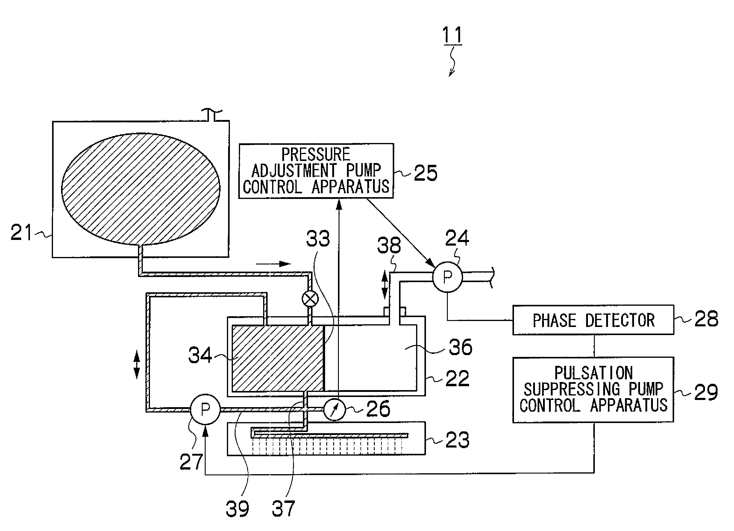
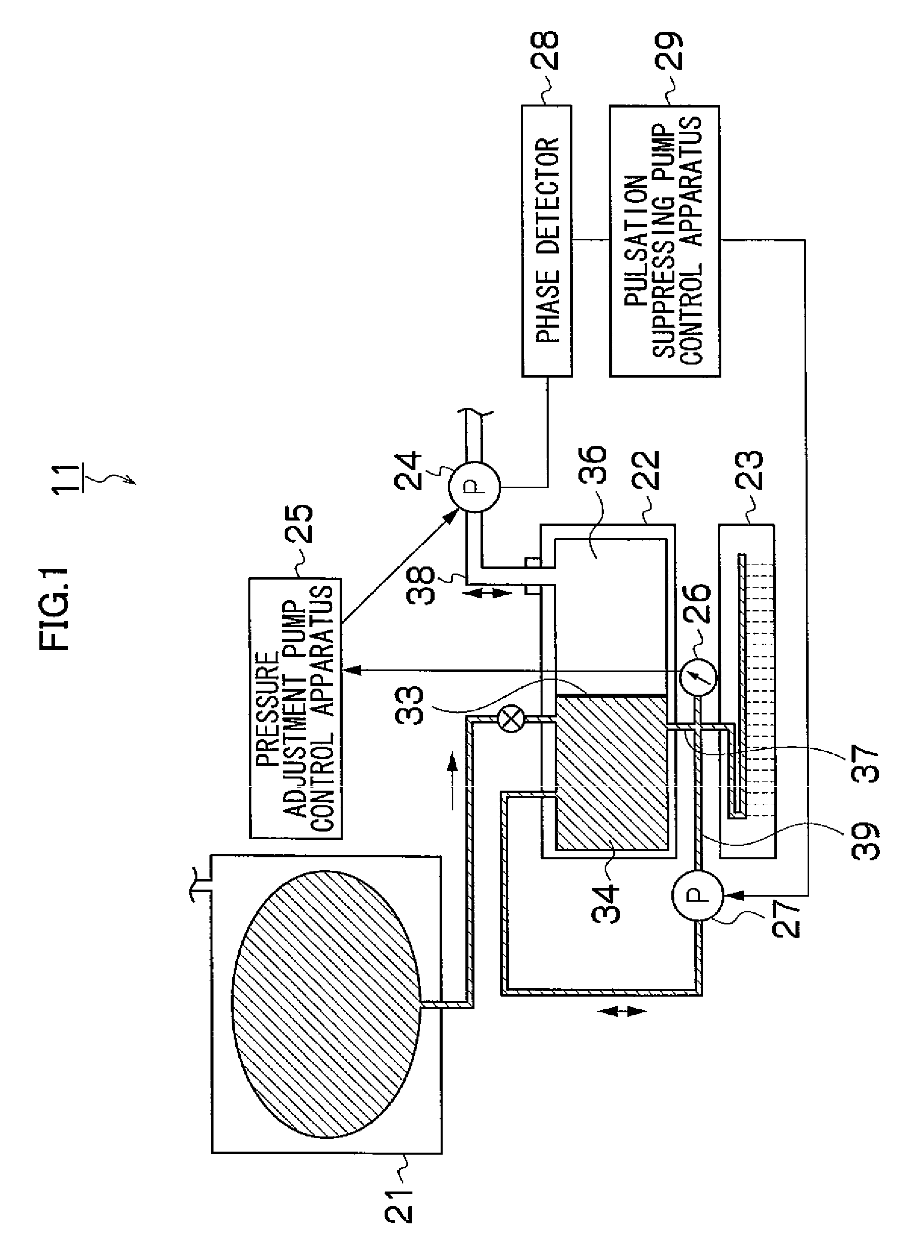
[0048]FIG. 1 is a general schematic diagram of a liquid ejection apparatus according to an embodiment of the present invention. As shown in FIG. 1, the liquid ejection apparatus 11 according to the present embodiment is constituted principally by a main tank 21 which stores ink, a sub tank 22 which temporarily stores ink supplied from the main tank 21, a recording head 23 which ejects ink supplied from the sub tank 22, and the like. The interior of the sub tank 22 is divided by a movable film 33 into an ink layer 34 and an air layer 36, and a pressure adjustment pump 24 for adjusting the pressure of the air layer 36 is provided in a pressure adjustment flow channel 38 which is connected to the air layer 36. Furthermore, a pressure gauge 26 is provided in the recording head flow channel 37 between the sub tank 22 and the recording head 23. A pressure adjustment pump control apparatus 25 is provided between the pressure adjustment pump 24 and t...

second embodiment

[0074]Next, the second embodiment will be described.

Composition of Liquid Ejection Apparatus

[0075]FIG. 10 is a schematic drawing of the liquid ejection apparatus 12 according to a second embodiment of the present invention. As shown in FIG. 10, the liquid ejection apparatus 12 according to the second embodiment differs from the liquid ejection apparatus 11 according to the first embodiment in that it comprises a liquid amount detector 31 and a correctional table storage apparatus 32. The liquid amount detector 31 is a detector which determines the amount of ink inside the sub tank 22, and it uses a laser displacement meter or density detector, or the like.

[0076]Furthermore, the correctional table storage apparatus 32 is an apparatus which stores a correctional table that is used in changing the amplitude of the output wave (waveform) of the pressure supplied by the pulsation suppressing pump 27, and controls the driving of the pulsation suppressing pump 27 in accordance with the amo...


PUM


Abstract

The liquid ejection apparatus includes: a recording head which ejects an ejection liquid; a liquid container which accommodates air and the ejection liquid; a recording head connection flow channel which leads from the liquid container to the recording head; a pressure determination device which determines pressure of the ejection liquid accommodated in the liquid container; a first pressure supply device which drives a rotating body to remove or introduce the air from or to the liquid container so as to keep pressure of the air in the liquid container constant; a phase determination device which determines a phase of the rotating body; a second pressure supply device which is disposed in a pulsation suppressing flow channel that connects the liquid container with the recording head connection flow channel and which removes and introduces the ejection liquid from or to the liquid container; and a control device which controls rotation speed of the second pressure supply device in accordance with the phase of the rotating body determined by the phase determination device so as to cancel out variation of the pressure of the ejection liquid caused by the first pressure supply device.

Description

BACKGROUND OF THE INVENTION[0001]1. Field of the Invention[0002]The present invention relates to a liquid ejection apparatus and a recording apparatus, and more particularly, to a liquid ejection apparatus in which pressure variation caused by the pulsating flow by a pump can be suppressed while maintaining the liquid refill volume and the responsiveness of pressure adjustment.[0003]2. Description of the Related Art[0004]Conventionally, in a liquid ejection apparatus, a negative pressure is applied to the liquid inside the nozzles, in order to prevent the liquid from leaking out from the nozzles when ejection is not being carried out. In order to apply such a negative pressure, a negative pressure generating chamber is provided, in an ink cartridge, an ink tank or a sub tank which is connected to the nozzles, in order to generate a negative pressure by adjusting the pressure through supplying and evacuating air by means of a pump. However, pumps generally have a pulsating action, an...

Claims


Application Information

Patent Timeline
Patent Type & Authority Patents(United States)
IPC IPC(8): B41J29/38
CPCB41J2/175B41J2/17509B41J2/17596
Inventor KOJIMA, TOSHIYAFURUKAWA, GENTARO
Owner FUJIFILM CORP
Why Eureka
Try Eureka