Shift position switching controller

a technology of shift position and switch controller, which is applied in the direction of mechanical equipment, digital data processing details, instruments, etc., can solve the problems of deteriorating the responsiveness of the shift position switch to the r position, and the n position check time may be left untouched/un-reduced, so as to reduce the shift position switch time and maintain the switching responsiveness

Active Publication Date: 2015-12-03
DENSO CORP
View PDF4 Cites 0 Cited by
  • Summary
  • Abstract
  • Description
  • Claims
  • Application Information

AI Technical Summary

Benefits of technology

[0008]It is an object of the present disclosure to provide a shift position switching controller that reduces a shift position switch time to the N position while maintaining switching responsiveness to positions other than the N position.

Problems solved by technology

That is, responsiveness of the switching of the shift position to the R position is deteriorated.
In such manner, if it is determined that the switching is likely to suffer from the deteriorated responsiveness if the N position check time is reduced, the N position check time may be left untouched / un-reduced.

Method used


Image

  • Shift position switching controller
  • Shift position switching controller
  • Shift position switching controller

Examples


Embodiment Construction

[0025]One example implementation of the present disclosure is hereafter described.

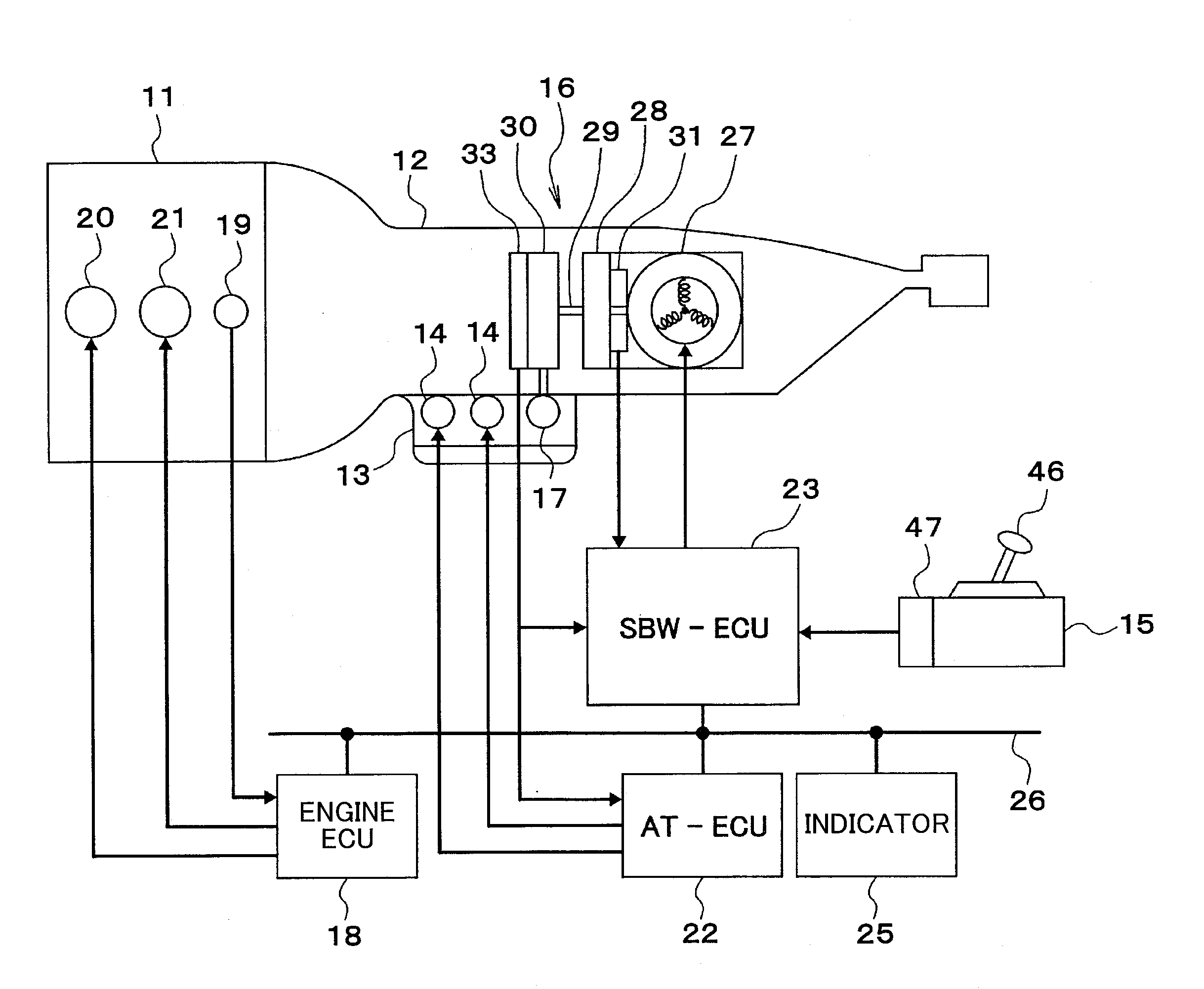
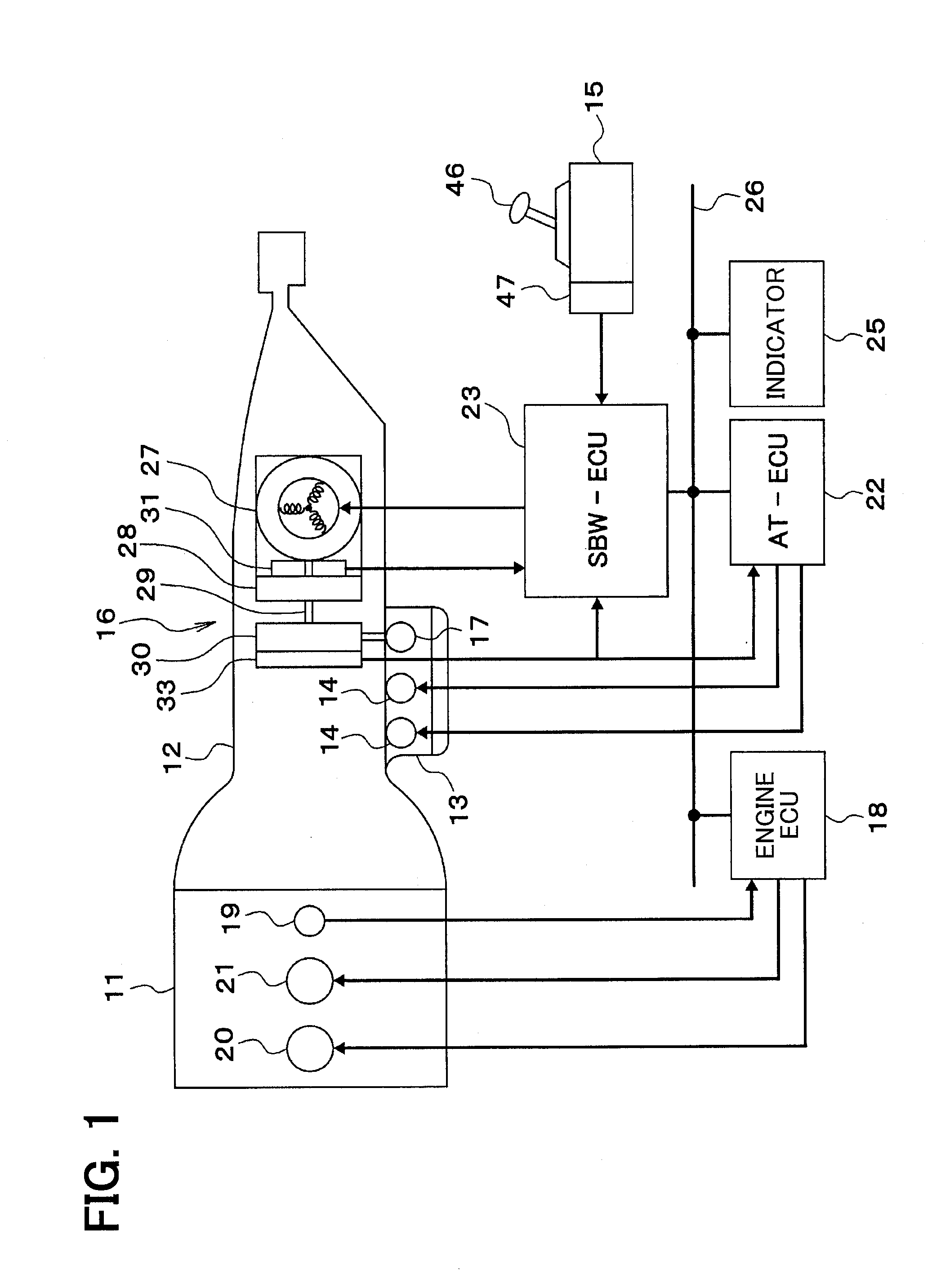
[0026]First, based on FIG. 1, an outline configuration of an automatic transmission controller system in vehicles is described.

[0027]The input shaft of an automatic transmission 12 is connected with the output shaft (i.e., a crankshaft) of an engine 11. The automatic transmission 12 is provided with the speed change gear mechanism (not shown) and a hydraulic control circuit 13. The speed change gear mechanism is provided with the friction engagement elements (not shown), such as plural clutches for switching a gear (i.e., for switching a gear ratio) and a brake. Further, the hydraulic control circuit 13 is provided with an oil pressure control valve 14 which controls the oil pressure applied to the friction engagement elements and a manual valve 17 which switches the hydraulic fluid circuit of the friction engagement elements. The manual valve 17 is driven by a position switching mechanism 16 according...


PUM


Abstract

A shift position switching controller determines whether the responsiveness for switching the shift position to an other-than-N position will be affected by a reduction of an N position check time and keeps the N position check time unchanged from a normal value if a current shift position is a D position or if a vehicle speed is equal to or greater than a preset value. Alternatively, the shift position switching controller determines whether the responsiveness of the controller will be affected by reducing the N position check time, and sets the N position check time to a shorter-than-normal value if the current shift position is a D position and the vehicle speed is equal to or greater than the preset value.

Description

CROSS REFERENCE TO RELATED APPLICATION[0001]The current application is based on and claims the benefit of priority of Japanese Patent Application No. 2014-114427, filed on Jun. 2, 2014, the disclosure of which is incorporated herein by reference.TECHNICAL FIELD[0002]The present disclosure generally relates to a shift position switching controller that switches shift positions using a motor.BACKGROUND INFORMATION[0003]In recent years, mechanical drive systems in vehicles have been gradually replaced by electrical drive-by-wire systems, in which components are driven by electric motors to improve space efficiency, assemblability, controllability, and the like. One example of such replacement may be found in a transmission shift position switching mechanisms. In such a system, when a target shift position is changed according to an operation of a shift control lever or the like, the shift position is controlled to be in the target shift position by rotating the motor to a target rotati...

Claims


Application Information

Patent Timeline
Patent Type & Authority Applications(United States)
IPC IPC(8): F16H61/32F16H59/44F16H61/18
CPCF16H61/32F16H2061/326F16H59/44F16H61/18F16H61/0213
Inventor KAWAGUCHI, YUUSAKUYOSHIDA, KAZUHIRO
Owner DENSO CORP
Why Eureka
Try Eureka