
Optical detector with DC compensation

A technology of optical detectors and photosensitive devices, which is applied in the field of optical detectors and optical detectors, and can solve problems such as performance degradation and bias voltage reduction

Inactive Publication Date: 2020-07-28
MELEXIS TECH NV
View PDF0 Cites 0 Cited by
  • Summary
  • Abstract
  • Description
  • Claims
  • Application Information

AI Technical Summary

Problems solved by technology

If background light generation exceeds 125µA, the bias voltage will be reduced by 1V, which may degrade performance

Method used


Image

  • Optical detector with DC compensation
  • Optical detector with DC compensation
  • Optical detector with DC compensation

Examples


Embodiment Construction

[0042] The present invention will be described with respect to particular embodiments and with reference to certain drawings but the invention is not limited thereto but only by the claims. The drawings described are only schematic and non-limiting. In the drawings, the size of some of the elements may be exaggerated and not drawn on scale for illustrative purposes. The dimensions and relative dimensions do not correspond to actual reductions to the practice of the invention.

[0043] The terms first, second, etc. in the description and in the claims are used to distinguish between similar elements and not necessarily to describe an order in time, space, hierarchy or in any other way. It is to be understood that the terms so used are interchangeable under appropriate circumstances and that the embodiments of the invention described herein are capable of operation in other sequences than described or illustrated herein.

[0044] It should be noted that the term "comprising", ...


PUM


Abstract

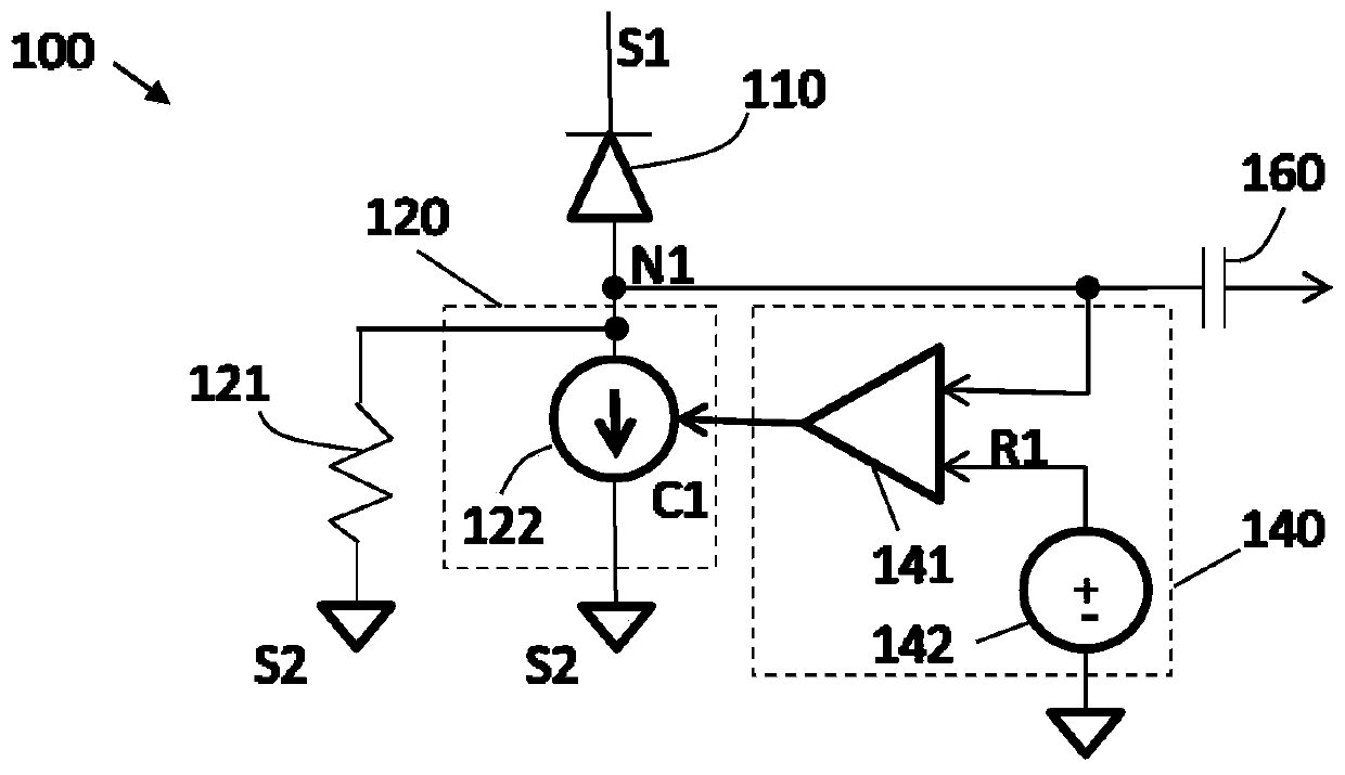
The invention discloses an optical detector with DC compensation. An optical detector (100), for converting an optical signal into an electrical signal. The optical detector (100) comprising a photo sensitive device (110) adapted for receiving the optical signal and converting it into an electrical signal. The optical detector moreover comprises a bias compensation circuit (120) and a control circuit (140). The control circuit (140) is adapted to control the bias compensation circuit to maintain a bias level across the photo sensitive device (110) above a minimum bias level, and to turn the bias compensation circuit (120) off when a current through the photo sensitive device (110) is so small that the bias level across the photo sensitive device (110) is above the minimum bias level.

Description

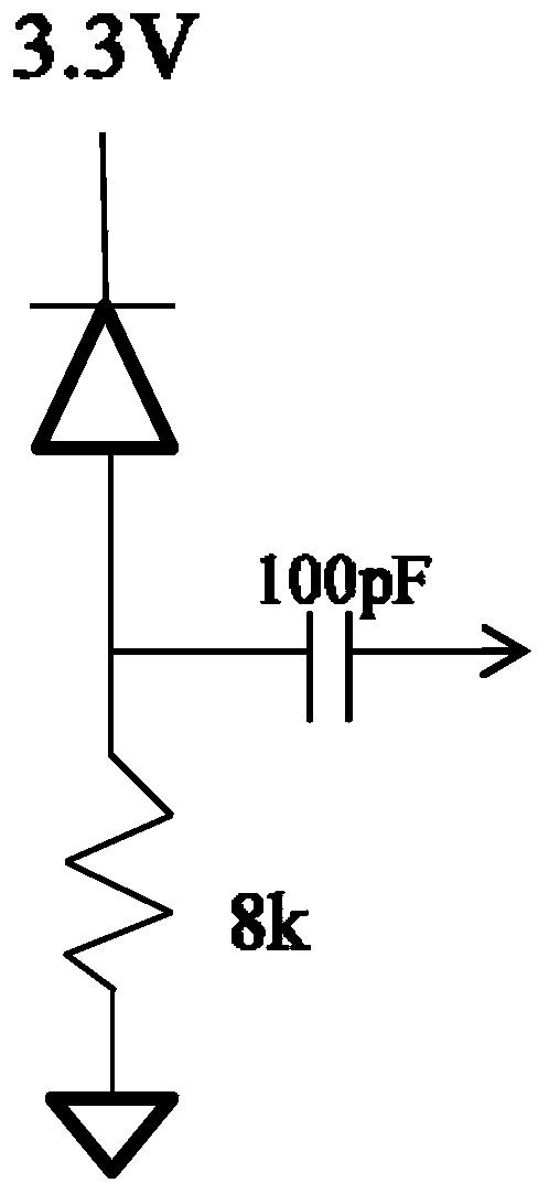
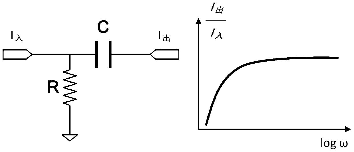
technical field [0001] The invention relates to the field of optical detectors. More specifically, it relates to the field of optical detectors adapted to increase the range of background light levels that can be tolerated. Background technique [0002] Photodiodes need to be biased to a voltage greater than some minimum bias level to function as specified. Passive bias systems (ie, simple resistors to ground) add minimal noise to the signal, but cannot maintain the required bias level if the background light generates significant DC bias current. If a smaller resistor is used, it can tolerate more background light, but the lower frequency corner of the signal passband will increase and the overall signal bandwidth will decrease. This significantly degrades the system response to signal pulses and reduces the system's ability to accurately detect small signals. [0003] The traditional biasing scheme illustrated in Figure 1 uses a series resistor to bias the photodiode. ...

Claims


Application Information

Patent Timeline
Patent Type & Authority Applications(China)
IPC IPC(8): H03F3/45G01S7/48G01S17/08
CPCG01S7/48G01S17/08H03F3/45H04B10/6911G01J1/44G01J2001/444G01S7/4861G01S17/10
Inventor D·利夫齐
Owner MELEXIS TECH NV
Learn More