Turbine engine with transverse-flow hydraulic turbine having reduced total lift force

a technology of hydraulic turbine and turbine engine, which is applied in the direction of machines/engines, reciprocating combination engines, electric generator control, etc., can solve the problems of turbine engine not being used in the construction of water turbine engines, and the problem is even more acu

Active Publication Date: 2011-01-13
INSTITUT NAT POLYTECHN DE GRENOBLE +1
View PDF6 Cites 25 Cited by
  • Summary
  • Abstract
  • Description
  • Claims
  • Application Information

AI Technical Summary

Benefits of technology

[0010]An embodiment provides a turbine engine comprising at least first, second, third, and fourth lift-type cross-flow water turbines, the first turbine comprising a first rotation shaft, the second turbine comprising a second rotation shaft, the first and second turbines being symmetrical to each other with respect to a plane, the third turbine comprising a third rotation shaft connected to the first rotation shaft by a first coupling device capable of compensating for spatial misalignments between the first and third rotation shafts, the third turbine forming, with the first turbine, a first stack of turbines, the fourth turbine comprising a fourth rotation shaft connected to the first rotation shaft by a second coupling device capable of compensating for spatial misalignments between the second and fourth rotation shafts, the third and fourth turbines being symmetrical to each other with respect to said plane, the fourth turbine forming, with the second turbine, a second stack of turbines. The turbine engine further comprises a device for holding the first and second turbine stacks, comprising a single vertical member symmetrical with respect to said plane or vertical members, each of said vertical members being symmetrical with respect to said plane and / or said vertical members being arranged symmetrically with respect to said plane, the holding device further comprising first and second plates symmetrical with respect to said plane, at least partly perpendicular to said plane, and arranged between the first and third turbines and between the second and fourth turbines, the first and second rotation shafts being pivotally connected to the first plate and the third and fourth rotation shafts being pivotally connected to the second plate. The turbine engine further comprises a control device capable of permanently maintaining the symmetry between the first and second turbine stacks with respect to said plane and of maintaining the rotation speeds of the first and second turbine stacks of equal values and of opposite rotation directions when the first and second turbine stacks are immersed in a moving liquid.
[0011]According to an embodiment of the present invention, at least one vertical member symmetrical with respect to said plane extends upstream of the first and second turbine stacks with respect to the liquid flow direction and forms a stem. The first turbine comprises first blades connected to the first rotation shaft. The second turbine comprises second blades connected to the second rotation shaft. The third turbine comprises third blades connected to the third rotation shaft. The fourth turbine comprises fourth blades connected to the fourth rotation shaft. The control device is capable of rotating the first, second, third, and fourth turbines so that the first, second, third, and fourth blades move up the flow of said liquid when they are closest to said plane.

Problems solved by technology

This problem is even more acute when several turbines are connected to one another to increase the recovered powers.
Such a turbine engine is not usable in the construction of a water turbine engine, given that lift forces are much stronger in a moving liquid.

Method used


Image

  • Turbine engine with transverse-flow hydraulic turbine having reduced total lift force
  • Turbine engine with transverse-flow hydraulic turbine having reduced total lift force
  • Turbine engine with transverse-flow hydraulic turbine having reduced total lift force

Examples


Embodiment Construction

[0041]For clarity, the same elements have been designated with the same reference numerals in the different drawings.

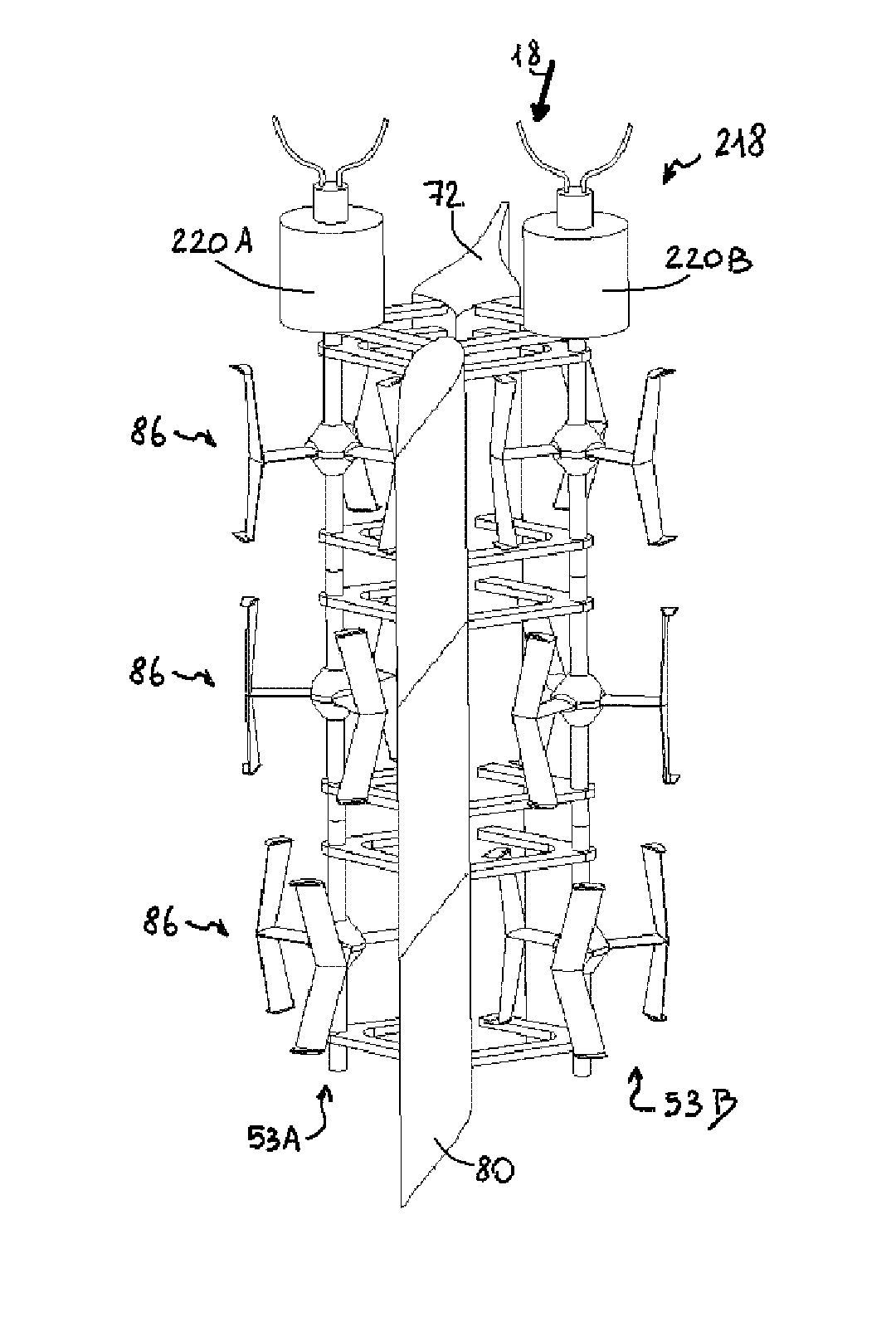
[0042]In the rest of the description, an elementary cross-flow turbine comprising a rotation shaft and means capable of rotating the shaft when these means are immersed in a liquid moving along a direction approximately perpendicular to the axis of the rotation shaft is called turbine unit.

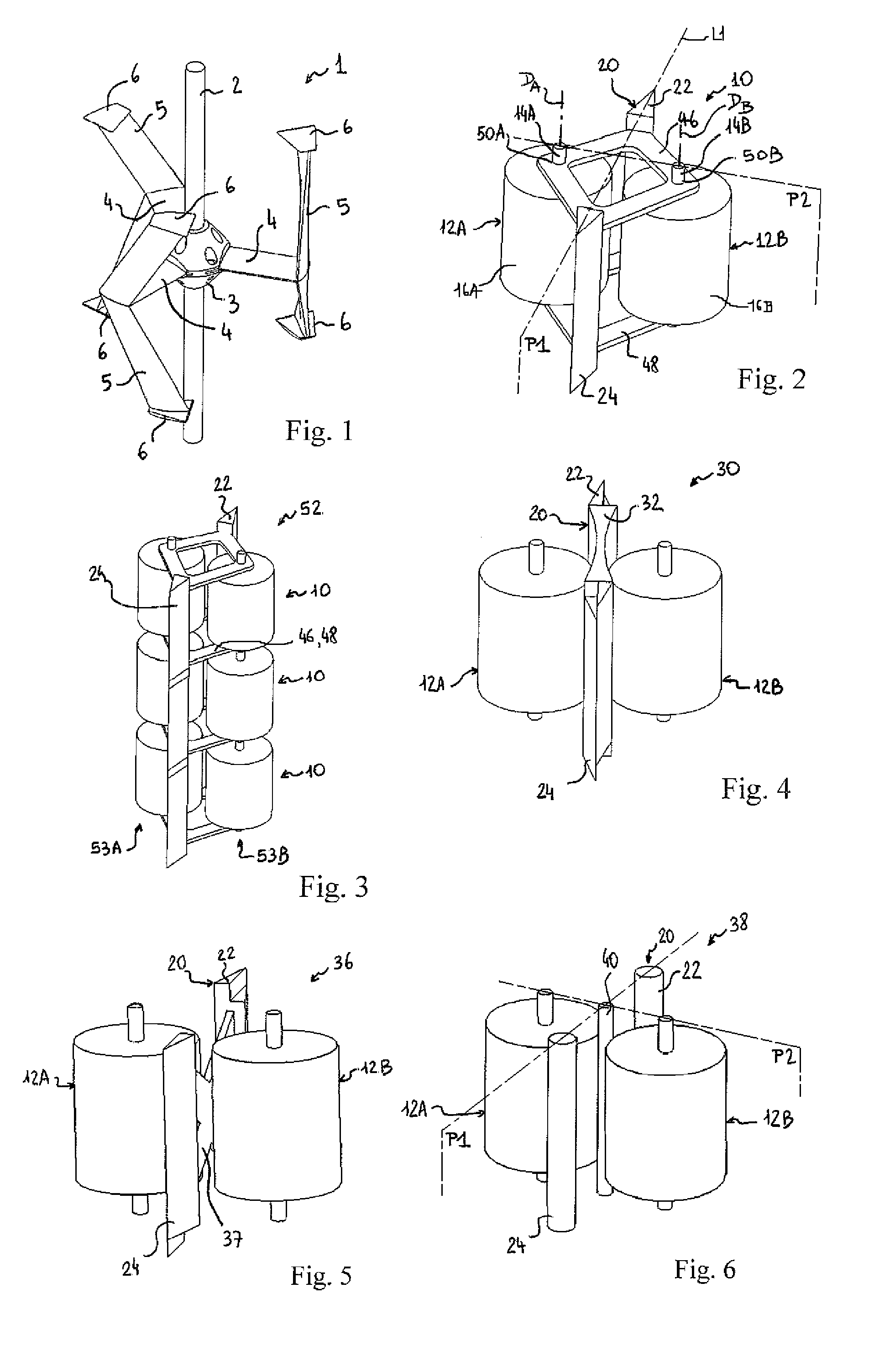
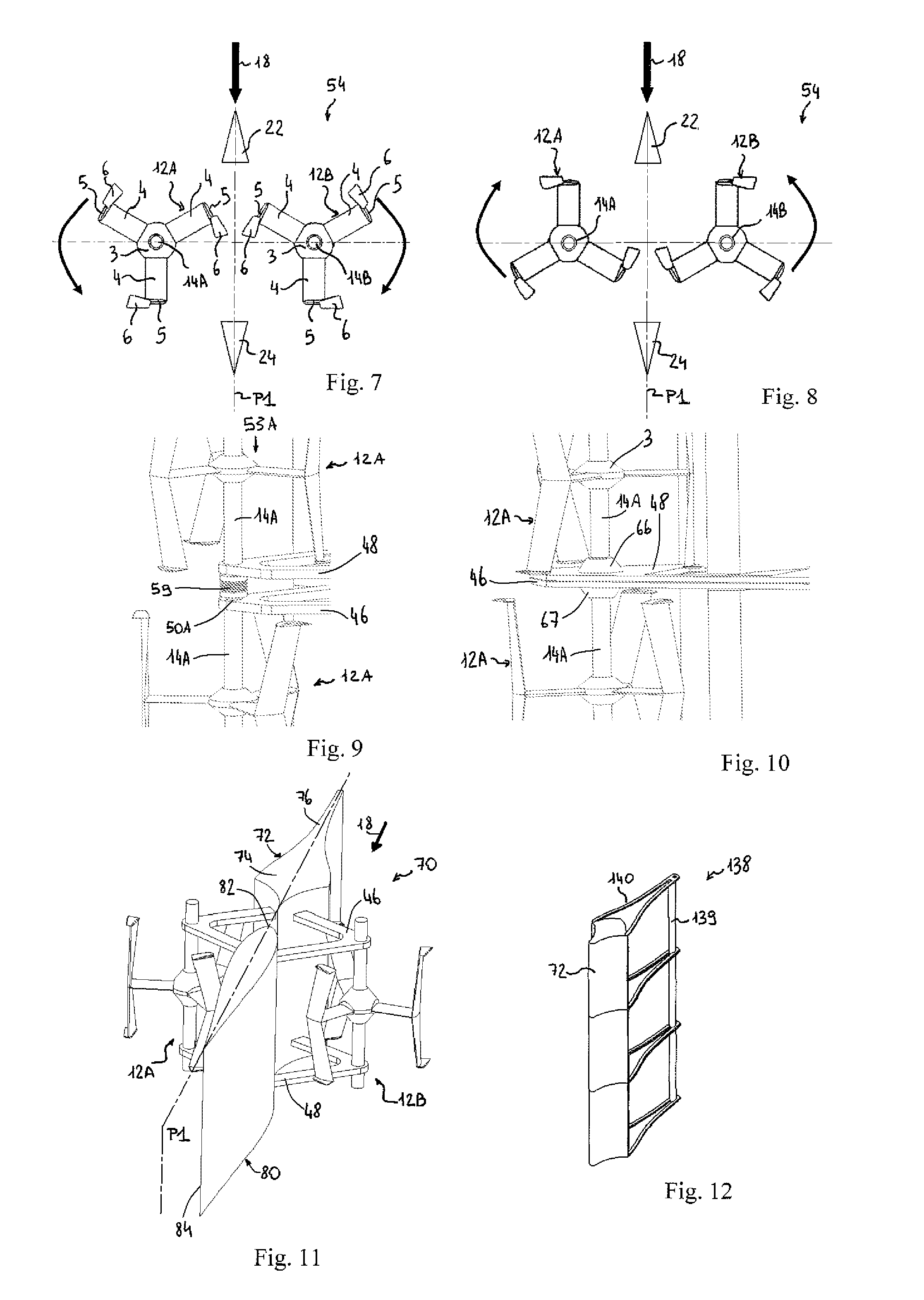
[0043]FIG. 1 shows an embodiment of a lift-type turbine unit 1, which corresponds to one of the embodiments described in European patent application EP1718863 filed by the Applicant. As an example, turbine unit 1 comprises a rotation shaft 2 and a hub 3 secured to rotation shaft 2 and from which arms 4 extend. Each arm 4 supports a foil 5 (or blade) at its end opposite to hub 3. Each foil 5, for example, V-shaped, may comprise winglets 6 at its ends.

[0044]A stack of several turbine units having their rotation shafts connected to one another and substantially aligned is called a turb...


PUM


Abstract

The invention relates to a turbine engine that includes at least first and second lift turbine stacks with transverse flow. The shafts of adjacent turbines in the first stack are connected by a first coupling device adapted for compensating space misalignments, and the shafts of adjacent turbines in the first stack are connected by a second coupling device adapted for compensating for space misalignments. The turbine engine includes a device for supporting the first and second turbine stacks, which is symmetrical to said plane, and a control device adapted for permanently maintaining the symmetry between the first and second turbine stacks relative to the plane, and for maintaining the rotation speeds of the first and second turbine stacks at equal values in opposite rotation directions.

Description

FIELD OF THE INVENTION[0001]The present invention relates to a water turbine engine and in particular to a water turbine engine for the recovery and the conversion of kinetic energy of sea or river currents, especially to provide electricity.DISCUSSION OF PRIOR ART[0002]Among clean natural sources of energy, a currently underexploited source of energy corresponds to water currents naturally present around the world: open sea currents, tidal currents, strait and estuary currents, river currents. Indeed, if hydroelectric plants providing electric power from the potential energy contained in impoundments (for example, dams on rivers) are widely spread, devices providing electric power directly from the kinetic energy of sea or river currents are generally still at the stage of draft.[0003]Although the sites that could be used to provide electric power from sea or river currents generally correspond to low current velocities, from 0.5 m / s to 6 m / s, the size of the sites and the large nu...

Claims


Application Information

Patent Timeline
Patent Type & Authority Applications(United States)
IPC IPC(8): F03B13/10F01K23/00
CPCF03B17/063F05B2240/93Y02E10/38Y10S415/907Y02E10/28Y02E10/30Y02E10/20
Inventor ACHARD, JEAN-LUCIMBAULT, DIDIERTOURABI, ALI
Owner INSTITUT NAT POLYTECHN DE GRENOBLE
Why Eureka
Try Eureka