[0007]This novel design for a Tension
Windmill will replace rigid
turbine blades with fabric Blades resembling twisted “sails”. This will dramatically increase the contact area presented to the wind, or sail area, and consequently the potential
power extraction from it. Unlike both rigid blade-type and other sail-type
windmill designs, the Blades of the present invention will be entirely loaded in tension, causing considerably less stress to the shaft while changing the nature of the force on the rotating members to eliminate bending forces.
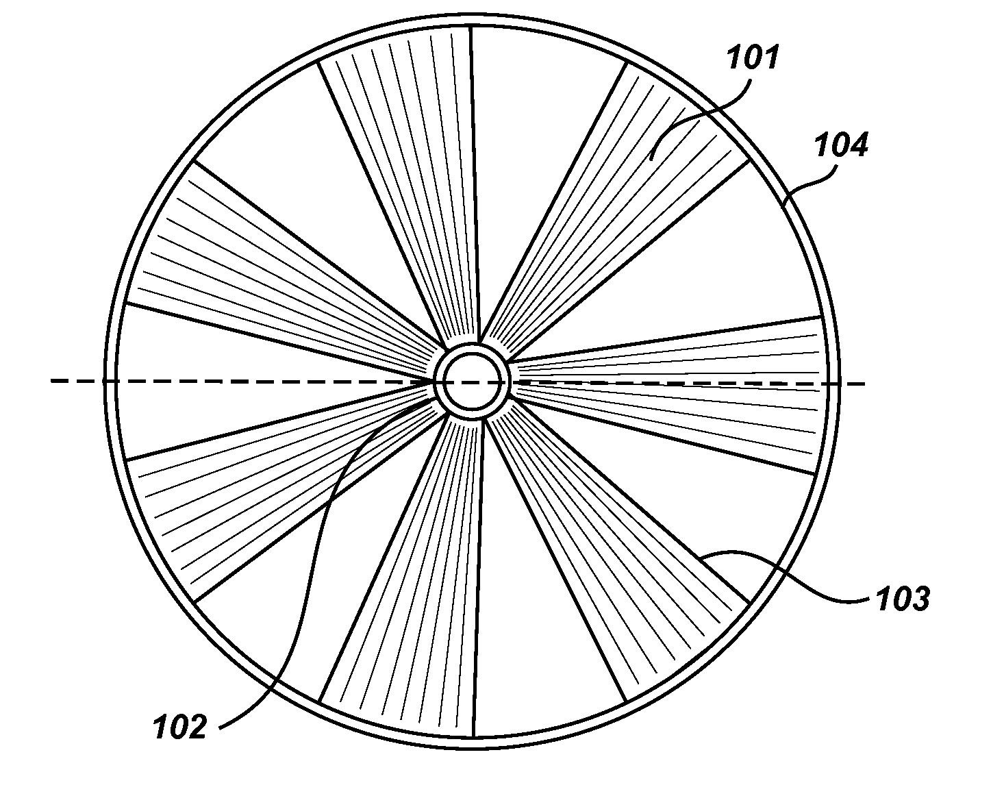
[0008]The Tension
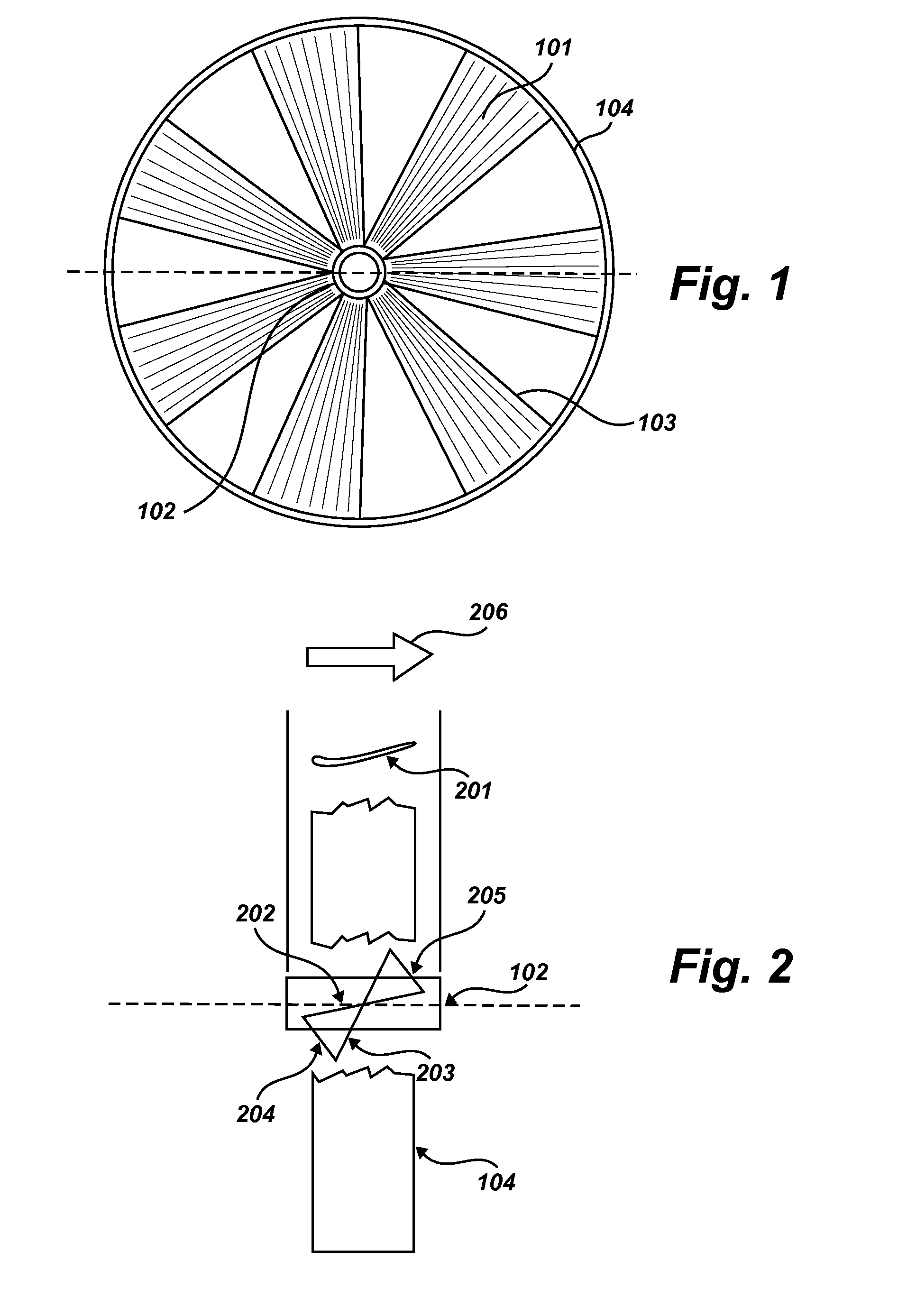
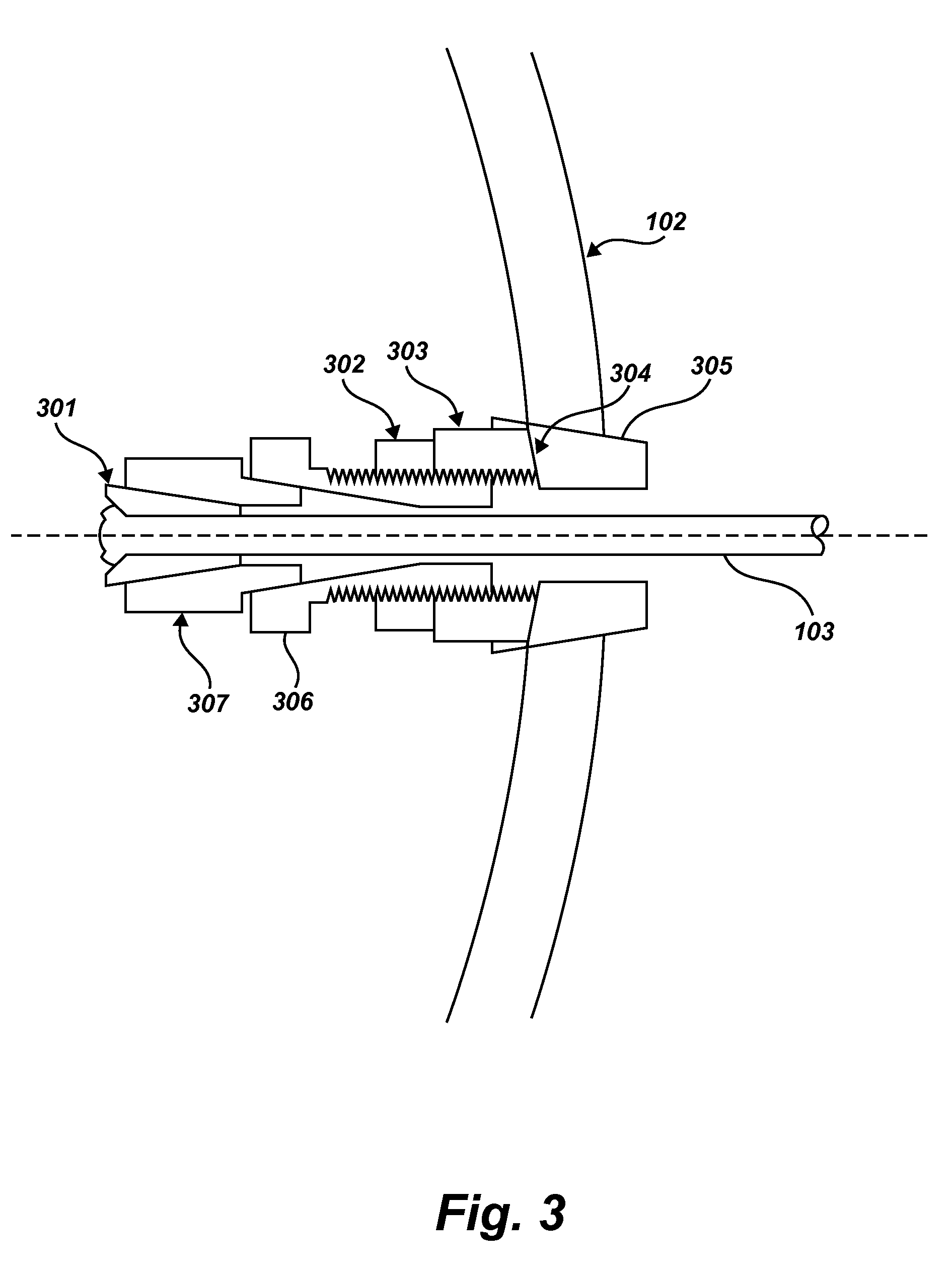
Windmill's mechanical structure consists primarily of a central Hub, a circular outer Rim, and a plurality of Blades between the Hub and Rim. Each Blade is constructed of a fabric material that can tolerate compound bends. This flat fabric is stretched between two Spokes, resembling the spokes of a bicycle wheel, which are attached at opposite ends to the Hub and Rim by clamps, distinguished by the respective labels H-Clamps and R-Clamps. The distance between the two Spokes for each Blade is nearly constant, but they are not aligned in parallel. The fabric between the Spokes is twisted into a shape that effectively accommodates a constant
wind speed at any radial distance from the Hub. This twist maintains a near-constant width in the fabric, but causes a smoothly varying
angle of attack (angle between the plane of the fabric and the
wind direction). The
angle of attack of any portion of the Blade is proportional to its distance from the Hub. This design maintains a smooth laminar flow of air when the Blade's rotation is slowed by the load (the electrical power generator). Therefore, there is a nearly
constant angular velocity at any
radius and the fabric Blade does not need to support bending moments. The shape also greatly increases the mechanism's sail area as compared to a rigid turbine of the same
diameter. The twisted shape and consequent radial variance of the
angle of attack are supported on both sides by the Blade's paired Spokes and thus maintains stability at any rotational speed. There is no need for springs or other devices designed to change the Blade's angle during its rotation about the Hub.
[0009]When rotating at speed, the Blades and Spokes are loaded in tension only. Tension members weigh dramatically less than equal-sized shapes that must support gravitational bending moments. Consequently, this design can be scaled to much larger dimensions than designs that use rigid blades attached to the hub as beams. Only two components of the entire design can be in compression: the Rim and the R-clamps, and such compression is moderate. During rotation, increased velocity creates increased centripetal acceleration which builds tensions throughout the Rim. Such tension relieves much of the compression on the R-Clamps and as a result, buckling can be prevented. The Hub of the Tension
Windmill supports a wider variety of forces, but its central location and relatively small size ensure that such forces are not problematic for functionality or efficiency.
[0010]The superiority of this design is perhaps most readily understood by comparing the fabric Blades to the sails of a sailboat. Like sails, the fabric Blades of the Tension Windmill are thin and present a large area to the wind, thus maintaining a very high
effective surface area to weight ratio and allowing for easy
scalability. The effect of having a greater sail area of the Blades is especially pronounced in light wind conditions, during which current wind turbine designs are particularly inefficient. The Blades can be constructed of many possible materials, two of which are sailcloth and woven fiberglass tubes. In contrast to other windmill designs which replace rigid blades with sail-like members, the fabric of the Tension Windmill's twisted Blades remain constantly supported on all sides.
[0011]The present invention is designed to be used with such controllers that allow movement non-synchronous to the AC line, and that regulate the torque delivered to the mechanism. The motion of each Tension Windmill should be controlled based on present wind conditions, as a function of
wind speed, in order to consistently maximize efficiency. The tension-loaded design of the Windmill allows the mechanism to withstand a very wide range of wind conditions without
threat of structural damage. Because the Blades are supported by tension, there are no bending forces when the Windmill is rotating at speed, and so increased wind speeds do not increase the gravitational loads borne by the Blades. During extremely heavy winds, when the output power would otherwise be greater than the
machine's rated power, the controlled windmill can be unloaded in torque, allowing the Blades to free-wheel and avoid unnecessary stress to the Hub or electro-
mechanical components.

