Impact wrench and control method for an impact wrench

Active Publication Date: 2010-10-21
HILTI AG
View PDF6 Cites 19 Cited by
  • Summary
  • Abstract
  • Description
  • Claims
  • Application Information

AI Technical Summary

Benefits of technology

[0010]An object of the present invention is to provide an impact wrench and a control method for an impact wre

Problems solved by technology

As described, one difficulty when screwing in a screw is that the properties of a subs

Method used


Image

  • Impact wrench and control method for an impact wrench
  • Impact wrench and control method for an impact wrench
  • Impact wrench and control method for an impact wrench

Examples


Embodiment Construction

[0028]Embodiments of control methods for screws are described hereafter for an illustrated impact wrench having a tangential impact mechanism as an example. The described adjustment methods may also be performed using differently designed impact wrenches, however.

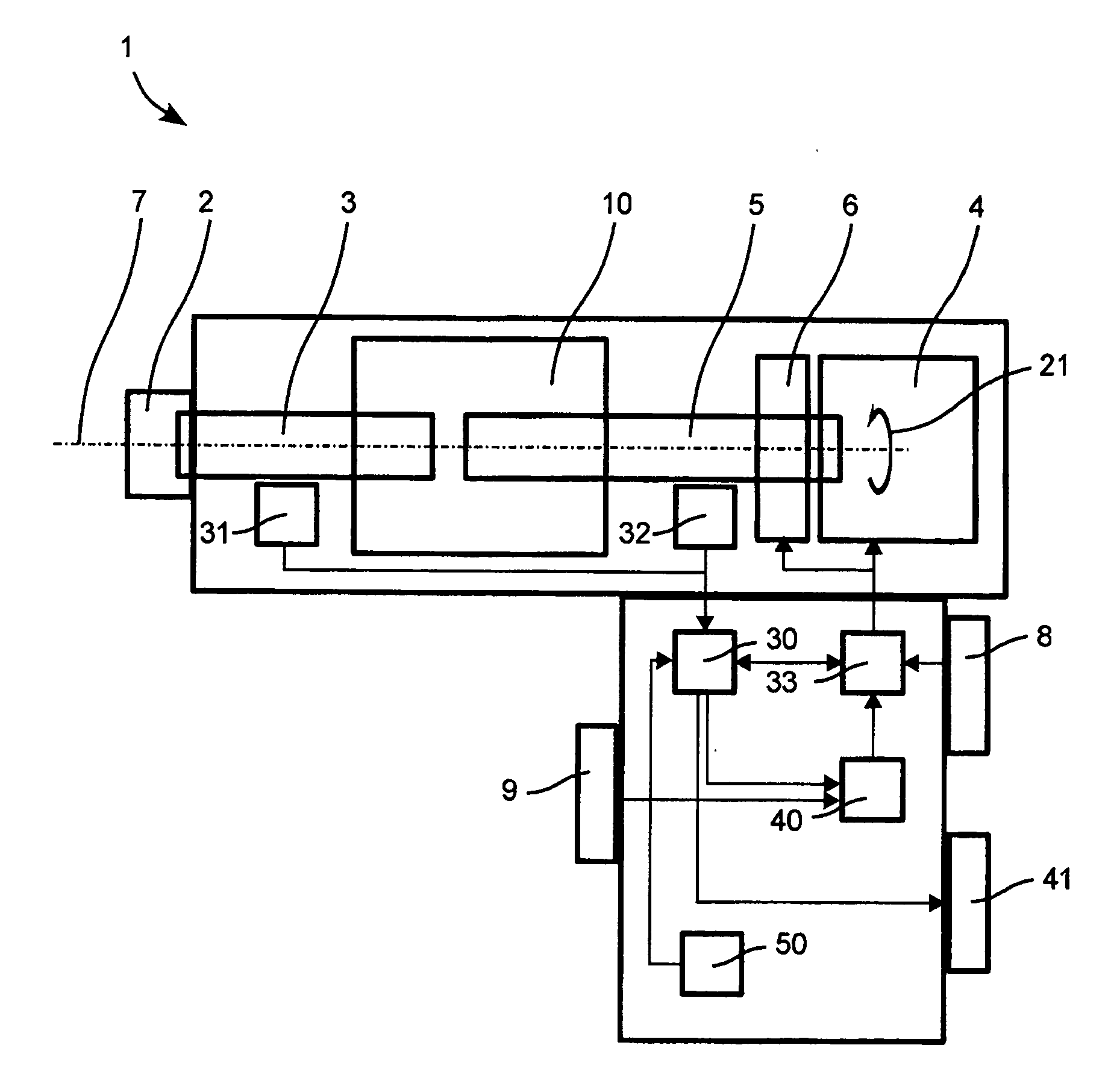
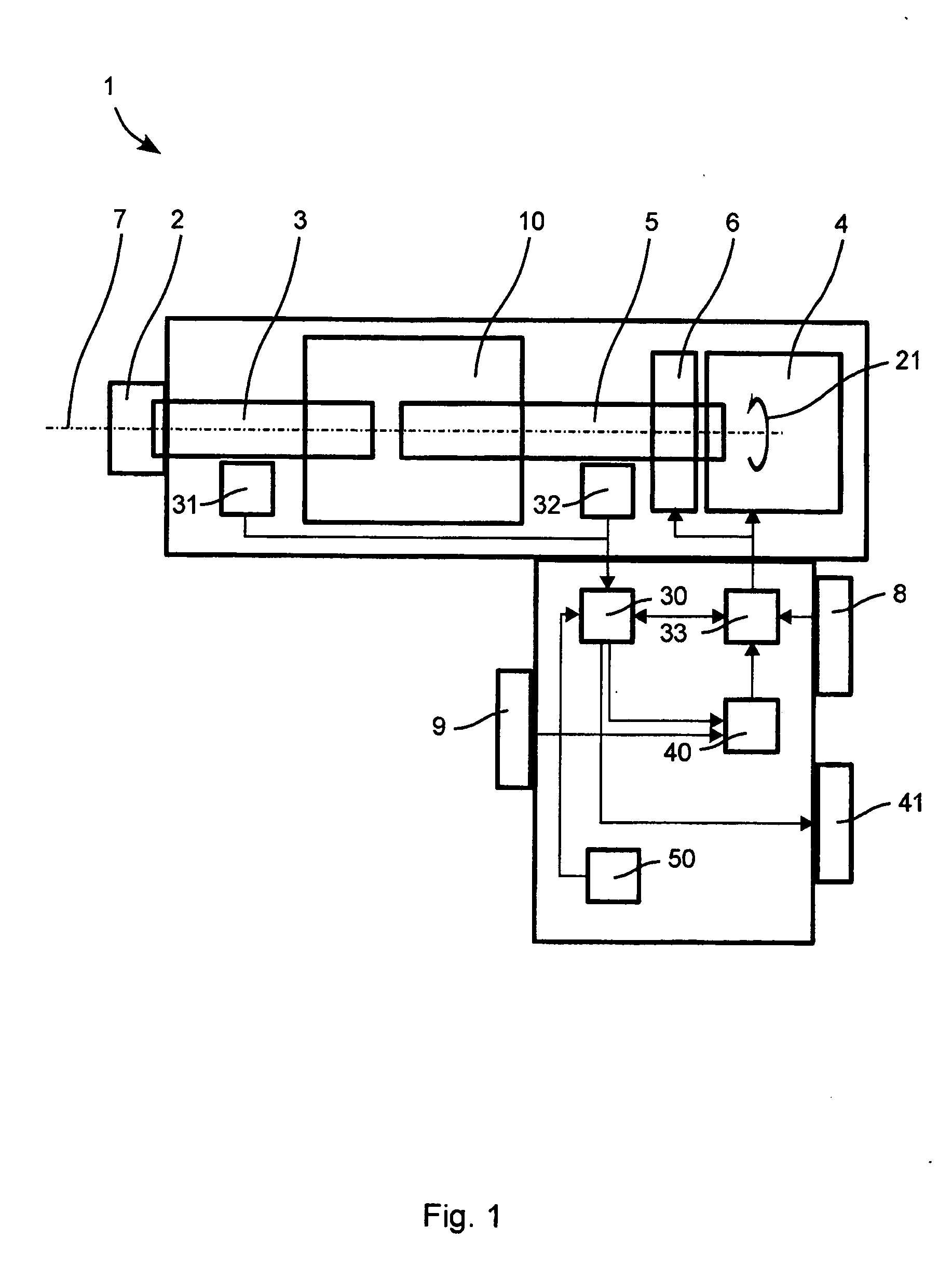
[0029]FIG. 1 schematically shows a design of an impact wrench 1.

[0030]A tool receptacle 2 is driven by an output shaft 3. A primary drive 4 drives a drive shaft 5. Primary drive 4 may be an electric motor, a pneumatic drive, etc. It may be advantageous to interpose a transmission 6 between primary drive 4 and drive shaft 5 to reduce the speed of drive shaft 5. Drive shaft 5 is permanently rotated in a rotational direction 21 around its longitudinal axis 7. The speed of primary drive 4 may be controlled by a motor controller 33. Motor controller 33 contains a rectifier for a brushless electric motor, for example, which is used as primary drive 4. The user may set the speed via an operating element 8. In a special design, it ...


PUM


Abstract

A control method according for an impact wrench includes ascertaining whether the impact wrench applies an impact when the drive shaft rotates in a lower speed range. The speed of the drive shaft then is increased to a higher speed range as a function of an ascertained impact during the rotation in the lower speed range.

Description

[0001]This claims the benefit of German Patent Application DE 10 2009 002 479.4, filed Apr. 20, 2010 and hereby incorporated by reference herein.[0002]The present invention relates to an impact wrench, in particular a tangential impact wrench, and a control method for an impact wrench.BACKGROUND[0003]A tangential impact wrench periodically, briefly provides a large tightening torque for tightening screw connections or for placing screw anchors. A continuous lesser torque is output at a handle or a holder of the tangential impact wrench, which the user or a stand must counteract.[0004]The tangential impact wrench is suitable for putting screws into manifold materials of varying hardness, for example, into stone, concrete, brick, limestone, and cellular concrete. Screws are typically inserted far enough that the screw head rests on a substrate (workpiece). The screw may not be tightened further, because this results in damage to the screw or the substrate. For example, the screw head ...

Claims


Application Information

Patent Timeline
IPC IPC(8): B25B21/02B23Q5/00
CPCB25B21/02B25B23/1405B25B23/14B25B23/1475
Inventor PROFUNSER, DIETERBRUGGER, PETERKUNTNER, JOCHEN
Owner HILTI AG
Why Eureka
Try Eureka