Locking mechanism for percussion musical instrument

a technology of a locking mechanism and a percussion instrument, which is applied in the direction of percussion musical instruments, instruments, musical instruments, etc., can solve the problems of over-complexity, inability of drummers to use their foot to operate other instruments, and inability to operate two bass drum pedals and a high hat pedal simultaneously

Inactive Publication Date: 2010-03-02
BILLDIDIT
View PDF6 Cites 12 Cited by
  • Summary
  • Abstract
  • Description
  • Claims
  • Application Information

AI Technical Summary

Benefits of technology

[0012]This mechanism is well adapted for use with the trip bar, but it nevertheless offers advantages over the prior art in terms of reliability and simplicity. The tilting of the upper mating flange releases the magnetic engagement and allows the upper cymbal to fall onto the lower cymbal in the closed position, yet also ensures quick re-engagement of the clutch when the upper collar component is brought back down onto the lower collar component by operating the foot pedal. As soon as the mating flanges come into engagement, the clutch re-engages without the need for any movable locking members or the like.

Problems solved by technology

This “ties up” one foot and makes it impossible for the drummer to use that foot to operate other instruments.
Since the drummer only has two feet, he or she cannot operate two bass drum pedals and a high hat pedal simultaneously.
These designs require action on the part of the drummer, leading to distraction, or are overly complex, see, for example, U.S. Pat. No. 5,028,776, or create additional clutter in the drummers playing area.

Method used


Image

  • Locking mechanism for percussion musical instrument
  • Locking mechanism for percussion musical instrument
  • Locking mechanism for percussion musical instrument

Examples


Embodiment Construction

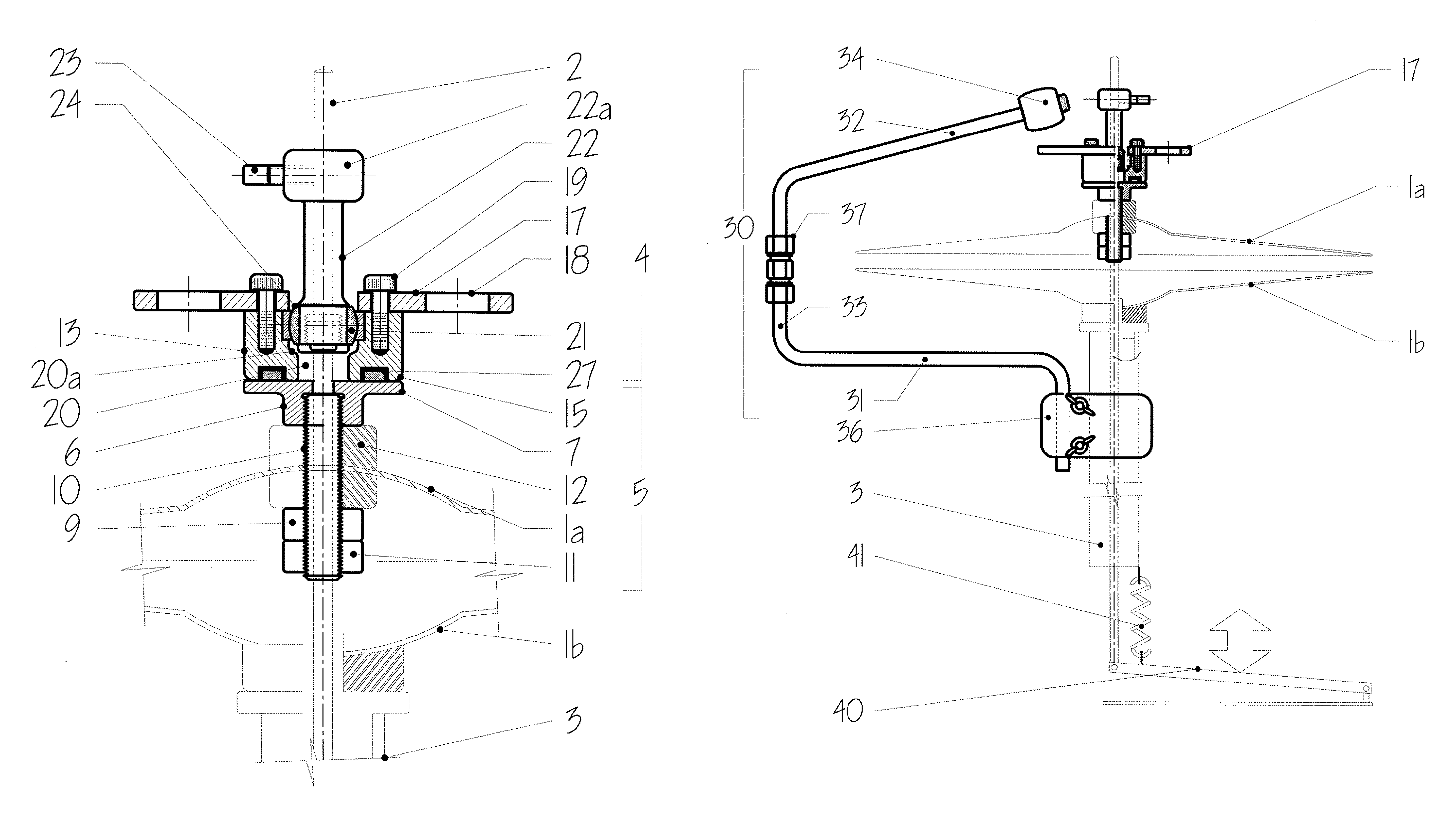
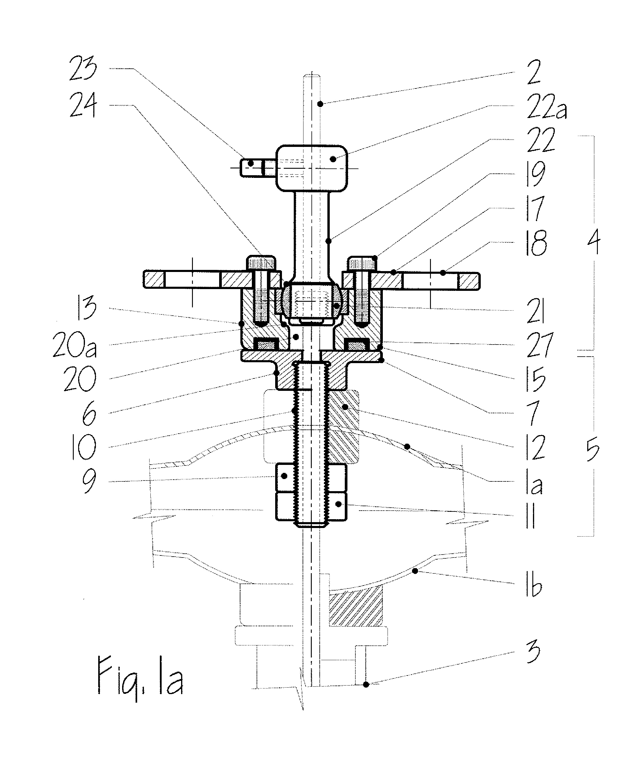
[0024]The locking mechanism shown in FIG. 1a comprises an upper cymbal 1a coupled to a control rod 2 and a lower cymbal 1b mounted on a tubular support 3 surrounding the control rod 2. The control rod 2 is moved up and down within the tubular support 3 by a foot-operated pedal 40 (FIGS. 5-7) and normally biased by a spring mechanism 41 into the raised position. Operation of the foot-pedal against the bias of the spring brings the upper cymbal 1a, when engaged with the control rod, down into contact with the lower cymbal 1b (the closed position). The operation of the control rod and foot pedal is not described in detail since it is conventional.

[0025]The locking mechanism comprises an upper collar component 4 locked to the control rod 2 and a lower collar component 5 attached to the upper cymbal 1a.

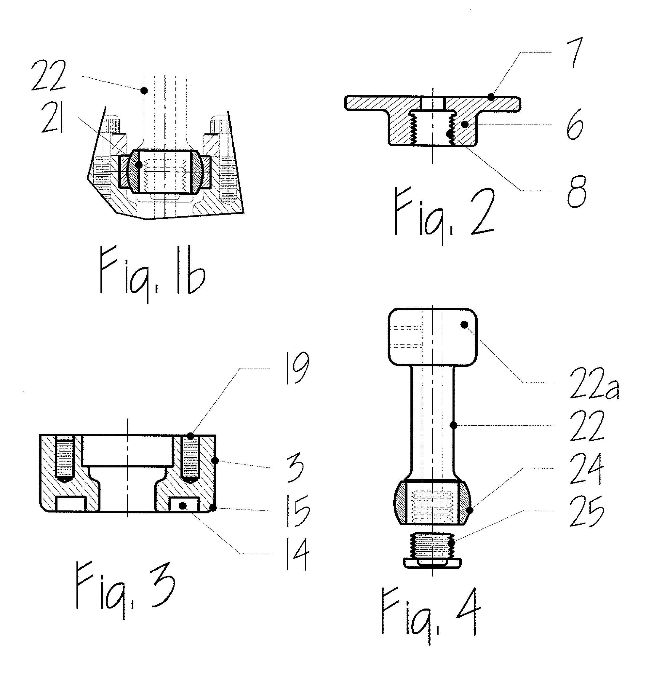
[0026]The lower collar component 5 comprises a mild steel mounting nut 6 with an upwardly facing lower mating flange 7 designed to be slidably fitted onto the control rod 2. In addition, ...


PUM


Abstract

A high hat cymbal has a magnetic clutch that engages the top cymbal and allows it to be controlled by a standard high hat foot pedal. When the drummer's foot is removed from the high hat foot pedal, the magnetic clutch strikes a mechanical arm which causes the magnetic clutch to disengage without any action required on the part of the drummer. The top cymbal can be re-engaged by the magnetic clutch so that the high hat foot pedal can now be operated again, simply by depressing the high hat foot pedal. A trip bar may be provided to provide for automatic disengagement of the clutch mechanism.

Description

FIELD OF THE INVENTION[0001]This invention relates to the field of percussion instruments, such as high hat cymbals, and in particular to a locking mechanism for use in such instruments.BACKGROUND OF THE INVENTION[0002]Most bands playing popular modern music will include a drummer, playing a drum set, also called a drum kit. The drum kit typically consists of a bass drum, snare drum, tom toms, cymbals, and a high hat cymbal. Modern drumming techniques have evolved significantly since the advent of rock and roll music in the 1950's. Modern drummers have a wide variety of percussive instruments, as well as the typical kit components, and they arrange these different instruments to suit their particular tastes and styles.[0003]A high hat cymbal actually consists of two cymbals facing each other. The high hat cymbal is struck by a drumstick, but is also operated using a foot pedal. The foot pedal operation consists of “closing and opening” the high hat, that is bringing the top cymbal i...

Claims


Application Information

Patent Timeline
Patent Type & Authority Patents(United States)
IPC IPC(8): G10D13/02
CPCG10D13/065
Inventor COADY, WILLIAM JOSEPH
Owner BILLDIDIT
Why Eureka
Try Eureka