Display device and display method

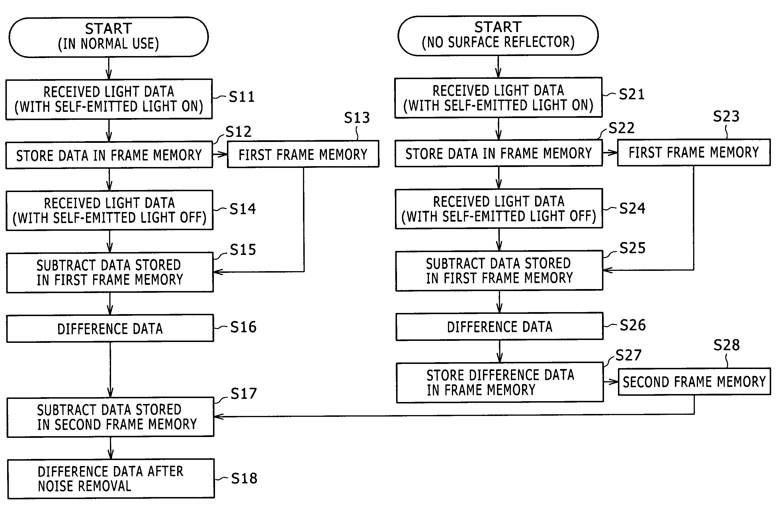
a display device and display method technology, applied in the field of display devices and display methods, can solve the problems of difficult to detect contact with the surface of the display device or the like under uniform light receiving conditions, noise is caused, and it is difficult to take such a measure easily, so as to eliminate the effect of internal reflection and excellent contact or proximity determination

Inactive Publication Date: 2010-03-02
JAPAN DISPLAY WEST
View PDF3 Cites 7 Cited by
  • Summary
  • Abstract
  • Description
  • Claims
  • Application Information

AI Technical Summary

Benefits of technology

[0014]The present invention has been made in view of such points. It is desirable to easily eliminate effects of extraneous light and noise when emitting light and receiving light simultaneously.
[0018]By subtracting the difference between the amount of received light in the light emitting state and the amount of received light in the non-light-emitting state which difference is stored as the initial value from the difference between the two amounts of received light, it is possible to eliminate effects of internal reflection in the display device, and determine contact with a corresponding position. Similar determination can be made for a state of proximity to the display surface.
[0019]According to the present invention, a state of contact with (or proximity to) a corresponding position can be determined on the basis of the difference between the two amounts of received light, and effects of internal reflection in the display device are eliminated by subtracting the stored initial value. It is therefore possible to make excellent contact or proximity determination unaffected by a use environment and the internal configuration of the device, with effects of extraneous light and effects inside the display device being eliminated.

Problems solved by technology

It is therefore difficult to detect contact with the surface of the display device or the like under uniform light receiving conditions.
However, it is difficult to take such a measure easily in an already proposed display device that emits light and receives light simultaneously.
In addition, noise is caused by an internal configuration of a light emitting part of the display device (for example noise caused by a backlight configuration of a liquid crystal display device).
Effects of the noise make it difficult to detect a contact position or a proximity position.

Method used


Image

  • Display device and display method
  • Display device and display method
  • Display device and display method

Examples


Embodiment Construction

[0035]A first embodiment of the present invention will hereinafter be described with reference to FIGS. 1 to 11.

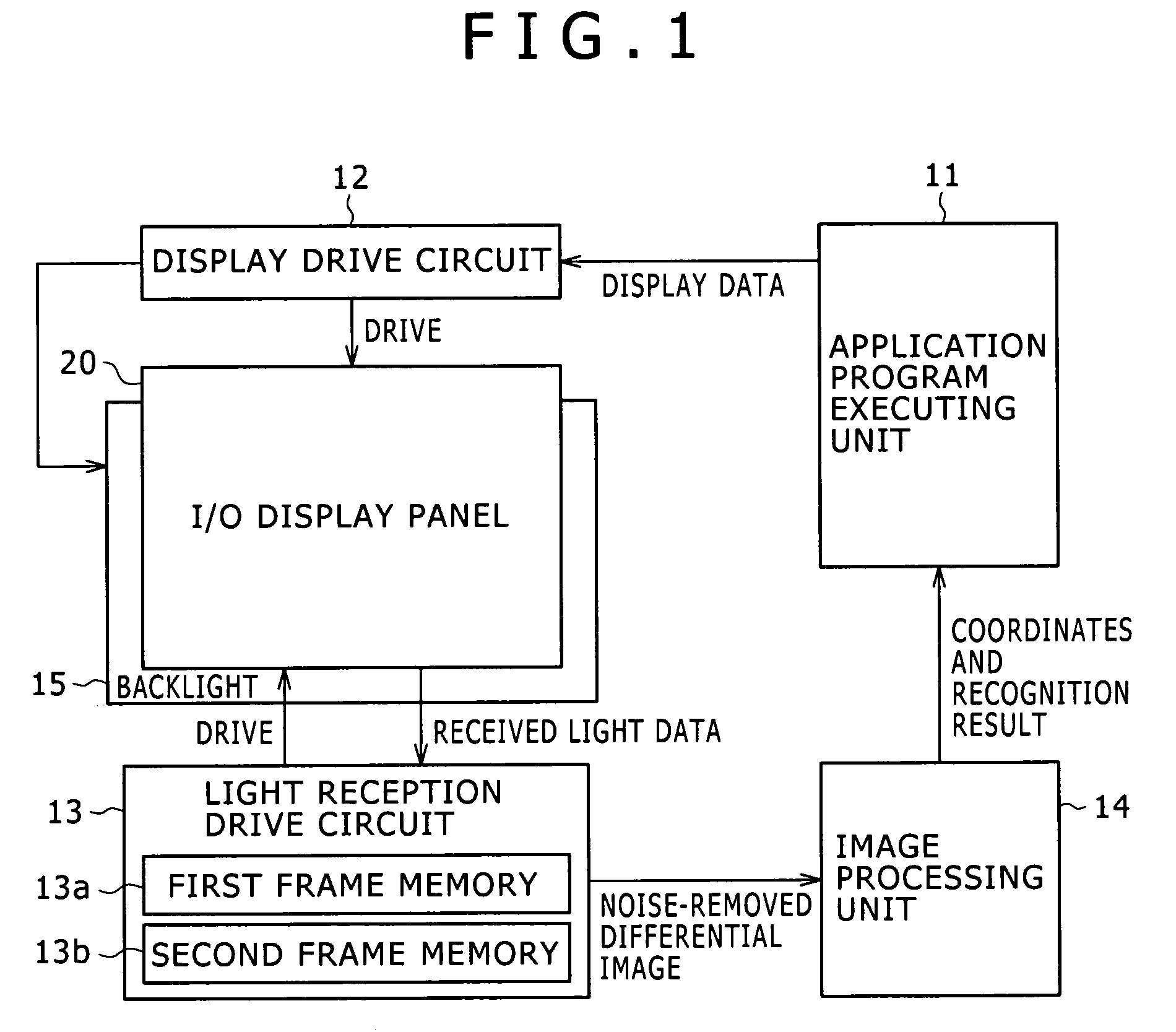
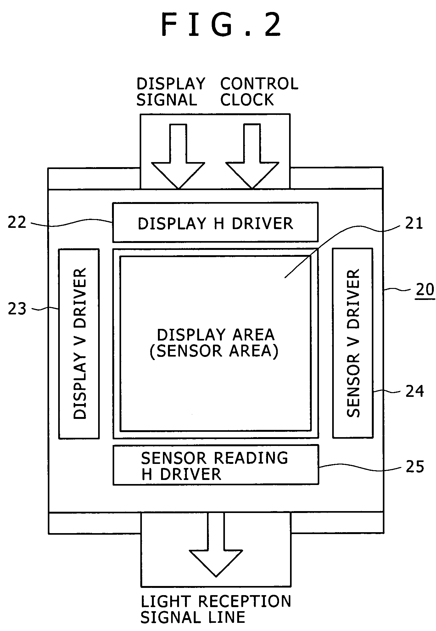
[0036]In this example, the present invention is applied to a display device formed as a liquid crystal display. A light receiving element is disposed adjacent to each light emitting element forming the liquid crystal display so that light emission (display) and light reception (reading) can be performed in parallel with each other. The display in this example that can perform the light emission and the light reception in parallel with each other will be referred to as an I / O display because the display can perform image input (light reception) and image output (display) simultaneously. In addition, as will be described later, the I / O display in this example can also detect not only an object in contact with a screen but also an object adjacent to the screen. Therefore contact detection in the following description includes proximity detection unless otherwise specified.

[00...


PUM


Abstract

The present invention includes a display device for displaying an image and receiving light simultaneously or alternately. The display device includes: a plurality of display elements for displaying the image on a display surface of the display device by emitting light; a plurality of light receiving elements for receiving light incident on the display surface formed by the display elements; a storing unit for storing, as an initial value, a difference between two amounts of light received by the light receiving elements; and a detecting unit for detecting a state of contact with or proximity to the display surface and subtracting the initial value stored by the storing unit from a difference between the two detected amounts of received light.

Description

CROSS REFERENCES TO RELATED APPLICATIONS[0001]The present invention contains subject matter related to Japanese Patent Application JP 2005-203259 filed in the Japanese Patent Office on Jul. 12, 2005, the entire contents of which being incorporated herein by reference.BACKGROUND OF THE INVENTION[0002]1. Field of the Invention[0003]The present invention relates to a display device and a display method suitable for application to a liquid crystal display and an organic EL (electroluminescence) display, for example, and particularly to display techniques that enable light reception in parallel with light emission.[0004]2. Description of the Related Art[0005]In related art, when a touch panel for allowing an operation by touching a display screen of a display device such as a television receiver or the like is formed on the display screen, the tough panel separate from the display device is put over the display screen.[0006]As a constitution using a separate touch panel, there is for exa...

Claims


Application Information

Patent Timeline
Patent Type & Authority Patents(United States)
IPC IPC(8): G06F3/041
CPCG06F3/0421G09G3/20G09G3/36G09G3/30G06F3/042
Inventor HARADA, TSUTOMU
Owner JAPAN DISPLAY WEST
Why Eureka
Try Eureka