
Motion sensor using dual camera inputs

a technology of motion sensor and input, which is applied in the field of motion sensor using dual camera input, can solve the problems of expensive hardware and complicated numerical processing techniques, time-consuming and laborious tasks, and inability to accurately measure the motion of a portable object,

Active Publication Date: 2010-03-02
ELECTRONICS ARTS INC
View PDF23 Cites 61 Cited by
  • Summary
  • Abstract
  • Description
  • Claims
  • Application Information

AI Technical Summary

Benefits of technology

This approach allows for accurate and cost-effective motion sensing in portable devices, including rotational detection, by processing images from multiple cameras to determine device motion, enhancing precision and reducing hardware costs.

Problems solved by technology

Sensing the motion of a device can be a time consuming task that requires intensive numerical processing.
Additionally, motion sensing may only provide a gross measure of the motion of a device.
Sensing motion of a portable object may require costly hardware and complicated numerical processing techniques.
Motion sensing using trilateration of positions, as performed by a Global Positioning System (GPS) or a hybrid position determination system, may be inadequate for sensing motion of a portable device.
A GPS system or hybrid position determination system typically provides inadequate precision to sense motion of a portable device.
GPS can require a great deal of time to acquire an initial position fix.
Additionally, a GPS system or hybrid position determination system typically cannot determine rotational motion of a portable device.
However, such systems are typically costly and not suitable for low cost designs.
The costs associated with gyroscopes used in motion sensing may exceed a perceived value of the entire portable device.

Method used


Image

  • Motion sensor using dual camera inputs
  • Motion sensor using dual camera inputs
  • Motion sensor using dual camera inputs

Examples


Embodiment Construction

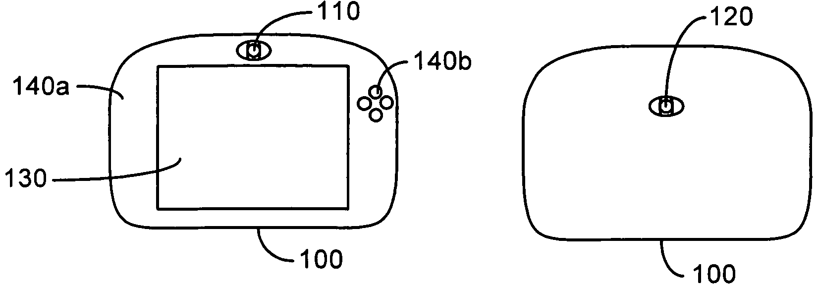
[0022]A portable device having motion sensing capabilities, and a method of sensing motion in a portable device are disclosed. The device and method use images captured from multiple cameras positioned along different viewing axis. The images captured by the multiple cameras can be processed to determine a direction of change. The direction of change in images captured from a first camera relative to the direction of change in images captured from a second camera can be used to sense motion of the device.

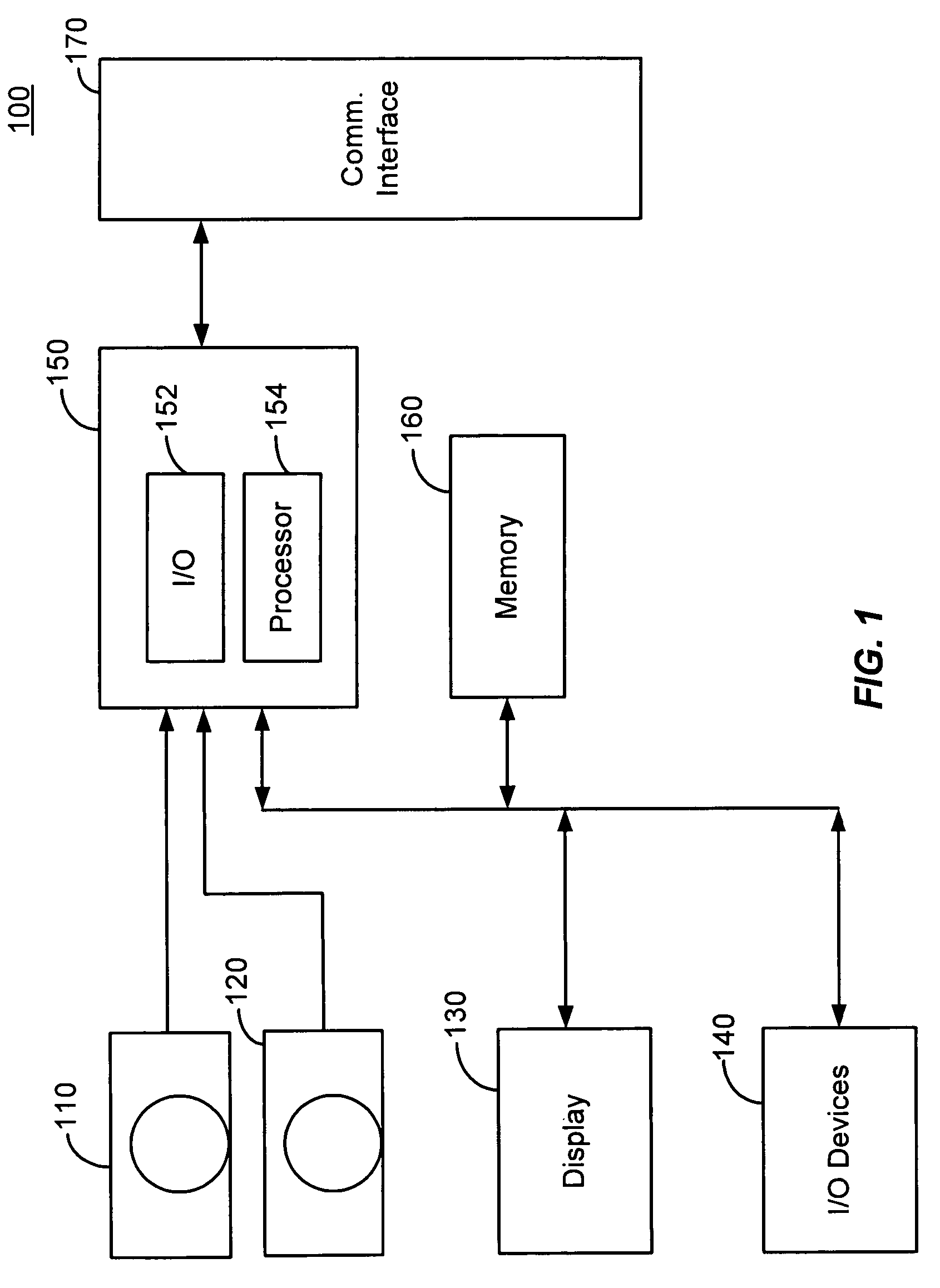
[0023]FIG. 1 is a functional block diagram of a motion sensing device 100. The device 100 includes a first camera and a second camera 120 coupled to a motion processing module 150. The motion processing module 150 can include, for example, an Input / Output (I / O) controller 152 and a processor 154. The motion processing module 150 can be coupled to memory 160, and can be coupled to a communication interface 170. The motion processing module 150 can also be coupled to a display 130 and...


PUM


Abstract

Motion sensing of a portable device using two cameras. A first camera is directed along a first viewing axis and a second camera is directed along a second viewing axis, different from the first viewing axis. The second viewing axis can be substantially opposite the first viewing axis. A motion processing module determines changes in images from the first camera and changes in images from the second camera. The motion processing module compares the direction of change determined from the first camera images relative to the direction of change determined from the second camera images. The motion processing module determines the motion of the portable device based in part on the comparison.

Description

BACKGROUND OF THE INVENTION[0001]Sensing the motion of a device can be a time consuming task that requires intensive numerical processing. Additionally, motion sensing may only provide a gross measure of the motion of a device. Sensing motion of a portable object may require costly hardware and complicated numerical processing techniques.[0002]Motion sensing using trilateration of positions, as performed by a Global Positioning System (GPS) or a hybrid position determination system, may be inadequate for sensing motion of a portable device. A GPS system or hybrid position determination system typically provides inadequate precision to sense motion of a portable device. GPS can require a great deal of time to acquire an initial position fix. Additionally, a GPS system or hybrid position determination system typically cannot determine rotational motion of a portable device.[0003]Motion sensing systems incorporating gyroscopes can be used to sense the motion of a portable device. Howev...

Claims


Application Information

Patent Timeline
Patent Type & Authority Patents(United States)
IPC IPC(8): H04N5/222A63F13/00A63F9/24G06F17/00G06F19/00H04N7/18G06T7/20
CPCH04N7/181G06T7/2086G06T7/285H04N7/18H04N7/188
Inventor HASHIMOTO, KAZUYUKI
Owner ELECTRONICS ARTS INC
Learn More