System and method to monitor particles removed from a component

a technology of particle removal and monitoring system, applied in the direction of cleaning using liquids, instruments, manufacturing tools, etc., can solve the problems of reducing the cleaning efficiency of the component, and affecting the cleaning effect of the component,

Active Publication Date: 2010-03-09
WESTERN DIGITAL TECH INC
View PDF4 Cites 30 Cited by
  • Summary
  • Abstract
  • Description
  • Claims
  • Application Information

AI Technical Summary

Problems solved by technology

Unfortunately, this commonly-used liquid solvent method, which utilizes ultrasonic energy, is frequency and power dependent and may either be ineffective at particle removal and / or may erode the very component that is being cleaned.
Further, this type of liquid solvent particle removal process for a component does not correlate well to the actual particle release from the component in the system as occurs in normal operation.
Moreover, the use of liquid solvents, such as chlorofluorocarbons and ketones, are environmentally hazardous and require numerous environmental safety procedures.

Method used


Image

  • System and method to monitor particles removed from a component
  • System and method to monitor particles removed from a component
  • System and method to monitor particles removed from a component

Examples


Embodiment Construction

[0016]In the following description, numerous specific details are set forth. However, it is understood that embodiments of the invention may be practiced without these specific details. In other instances, well-known circuits, structures, and techniques have not been shown in order not to obscure the understanding of this description.

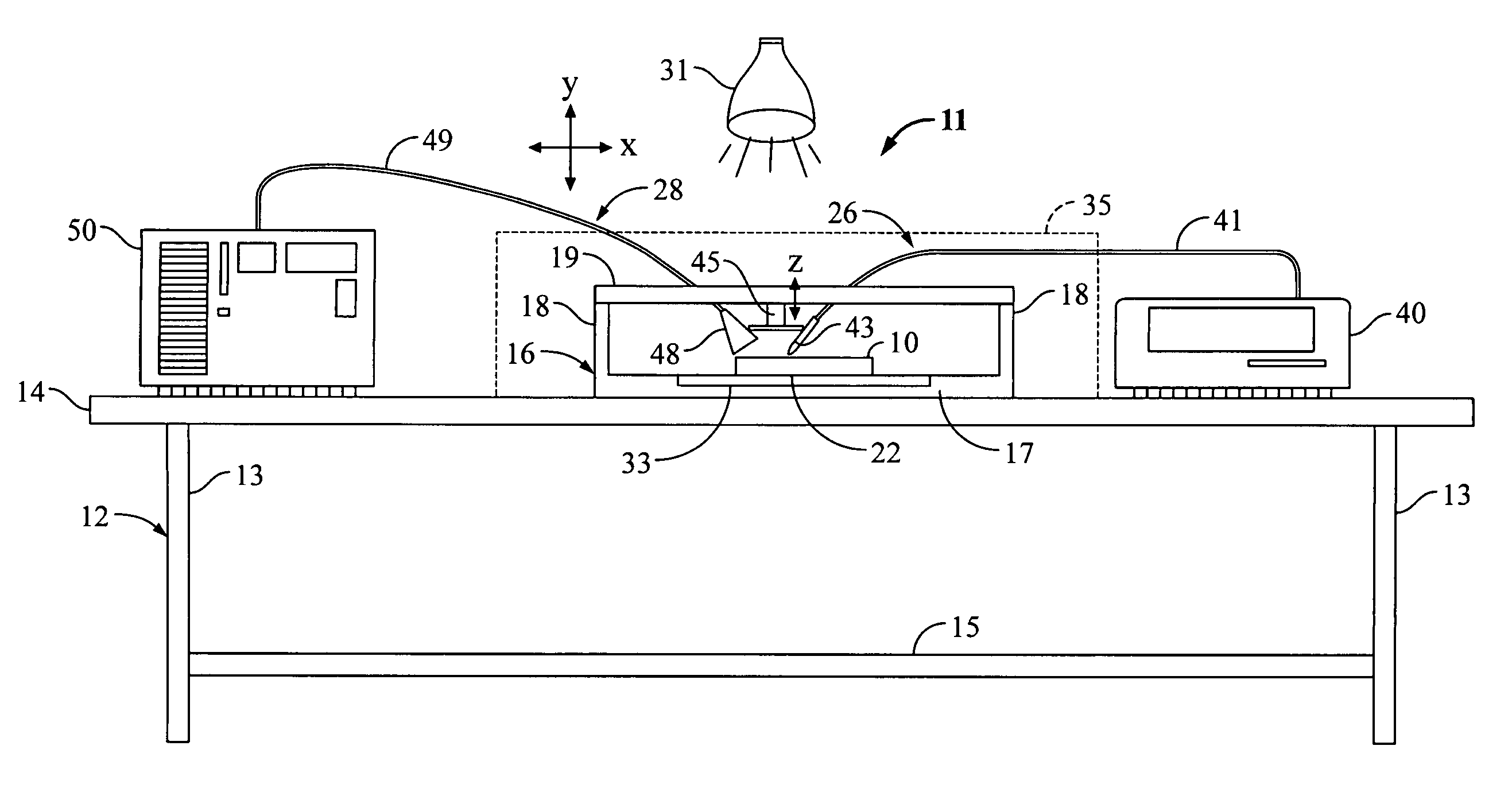
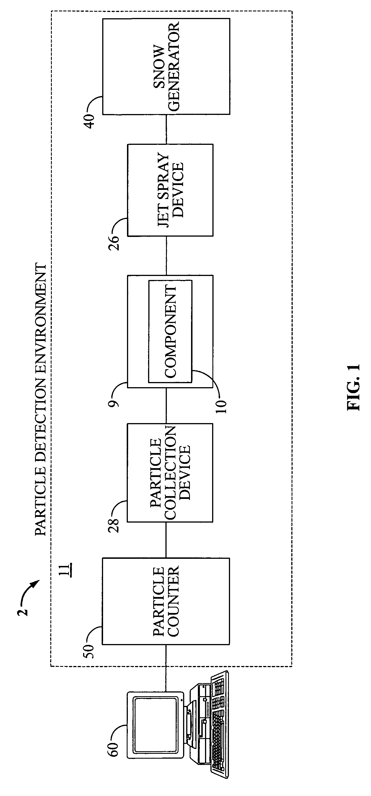
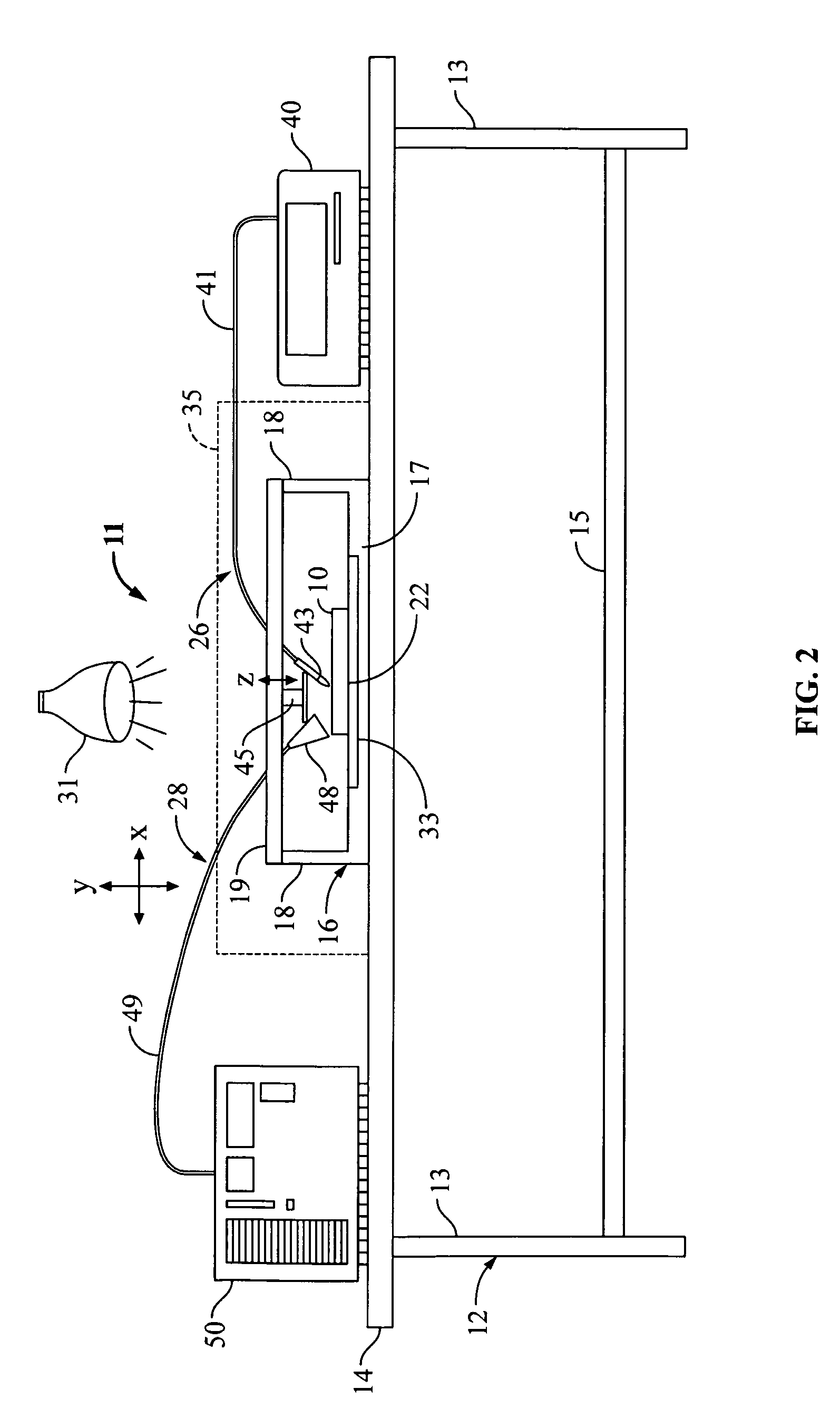
[0017]With reference now to FIG. 1, FIG. 1 is a block diagram of a particle monitoring system 2 to monitor and count particles removed from a component, according to one embodiment of the present invention. In particular, the particle monitoring system 2 may include a particle detection environment 11 and, optionally, a computer 60.

[0018]The particle detection environment 11 may include a holding platform 9 to hold a component 10 to be cleaned. Further, the particle detection environment 11 may include a jet spray device 26 having an outlet that is disposed locally relative the component 10 and a snow generator 40 that is operable to generate cleaning s...


PUM

PropertyMeasurementUnit
volumeaaaaaaaaaa
heataaaaaaaaaa
particle sizeaaaaaaaaaa

Abstract

Disclosed is a system and method to monitor and count particles removed from a component. The particle monitoring system includes a jet spray device, a snow generator, a particle collection device, and a particle counter. The jet spray device includes an outlet that is disposed locally relative to the component. The snow generator is operable to generate cleaning snow comprising a stream of ice particles, wherein the cleaning snow is emitted from the outlet of the jet spray device onto the component to cause the ejection of particles from the component. The particle collection device includes a collector that is disposed locally around the component to collect particles ejected from the component. The particle counter is coupled to, and in fluid communication with, the particle collection device. The particle counter is operable to detect and count particles ejected from the component.

Description

BACKGROUND[0001]1. Field of the Invention[0002]The present invention relates to a system and method to monitor particles removed from a component.[0003]2. Description of the Prior Art and Related Information[0004]Precision optical, mechanical, and electronic components for use in electro-optical, electro-mechanical, electronic systems, and combinations thereof, need to be cleaned prior to assembly, in order to reduce the amount of contaminant particles that are introduced into these often highly sensitive systems. Further, it is important to be able to monitor, count, and characterize removed contaminant particles from the components that are utilized in such systems. This is especially true for highly sensitive storage systems, such as disk drives.[0005]Today, many contaminant particle removal and monitoring systems utilize liquid solvents and ultrasonic energy in order to remove and monitor contaminant particles. For example, in these types of systems, a component is typically sus...

Claims


Application Information

Patent Timeline
Patent Type & Authority Patents(United States)
IPC IPC(8): B08B7/00
CPCB08B7/02B24C1/003B24C3/322B24C9/003G01N1/2202G01N1/44
Inventor BOYNTON, RUDY C.FLYNN, PATRICK E.WEBB, PAUL W.KNOTH, GARY W.
Owner WESTERN DIGITAL TECH INC
Why Eureka
Try Eureka