Digital lock detector for phase-locked loop

a phase lock and detector technology, applied in the direction of phase difference detection, angle demodulation, automatic control, etc., can solve the problems of difficult to obtain precise lock indication through this structure, unstable analog lock detectors, etc., and achieve the effect of saving circuitry area and improving lock precision

Active Publication Date: 2010-03-09
VIA TECH INC
View PDF7 Cites 11 Cited by
  • Summary
  • Abstract
  • Description
  • Claims
  • Application Information

AI Technical Summary

Benefits of technology

[0010]The invention constructs a predetermined time window with a lead clock and a lag clock. When the second clock successively transitions in the predetermined time window for N times, a match detector generates a match signal to indicate a lock state. When the second clock successively transitions outside the time window for M times, the match detector generates an unlock signal to indicated an unlock state. The invention provides a digital lock detector such that a lock precision is improved and circuitry area is saved.

Problems solved by technology

Therefore, a precise lock indication is difficult to be obtained through this structure.
Some conventional lock detectors are implemented with analog circuits, which include resistors and capacitors susceptible to variations of process, temperature and power supply voltage, rendering the analog lock detectors unstable.

Method used


Image

  • Digital lock detector for phase-locked loop
  • Digital lock detector for phase-locked loop
  • Digital lock detector for phase-locked loop

Examples


Embodiment Construction

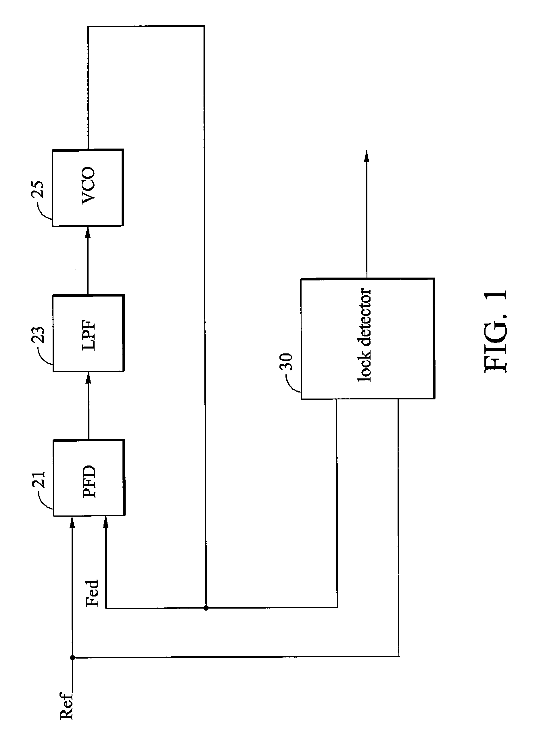
[0022]FIG. 1 is a block diagram of a phase locked-loop with a digital lock detector according to an embodiment of the invention. The phase locked-loop includes a phase frequency detector 21, a low pass filter 23, a voltage controlled oscillator 25 and a digital lock detector 30. A loop formed by the phase frequency detector 21, the low pass filter 23, and the voltage controlled oscillator 25 receives a reference clock Ref and generates a feedback clock Fed. The digital lock detector 30 detects whether the phase locked-loop is in a lock state and generates a lock signal to indicate the feedback clock Fed enter a lock state.

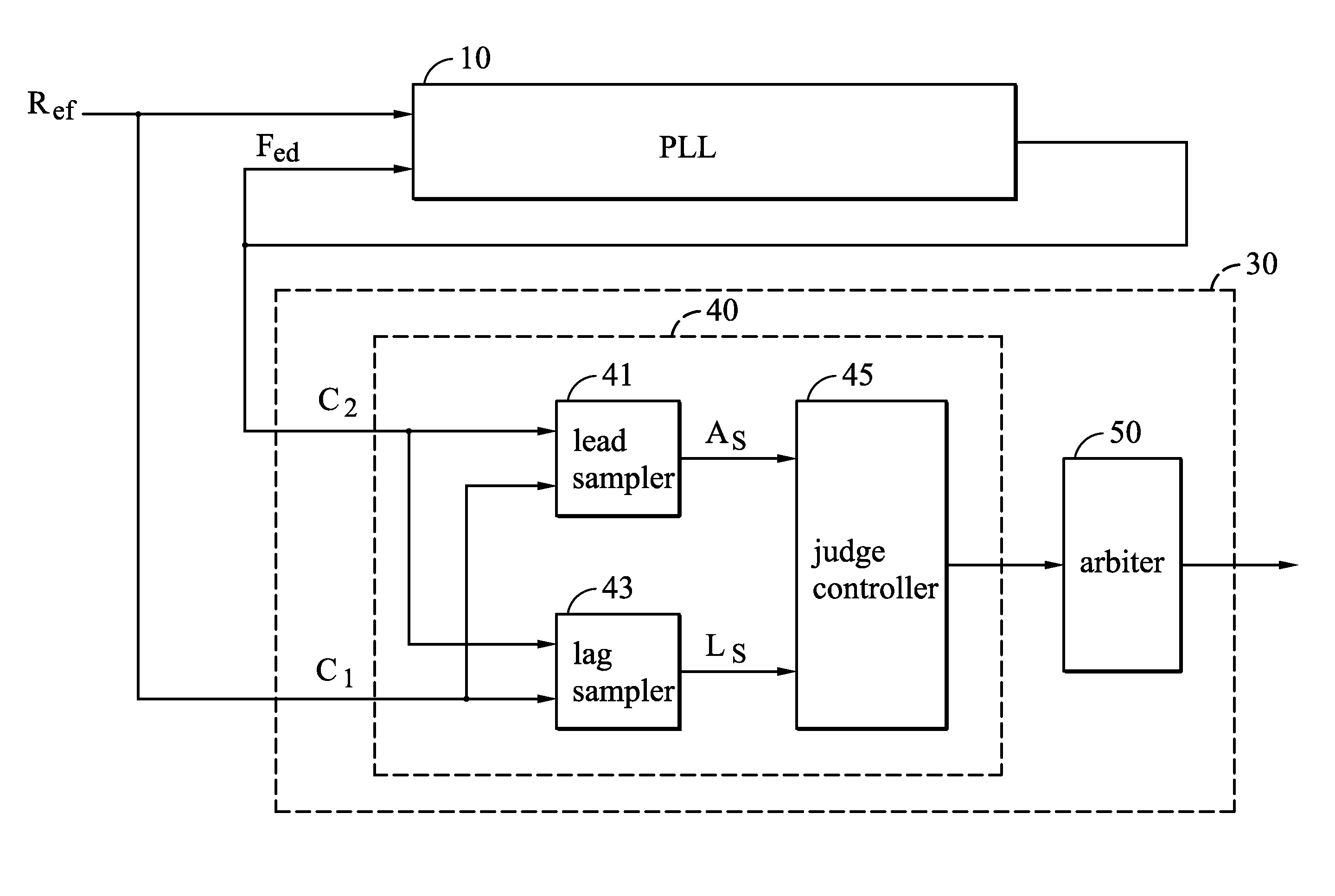
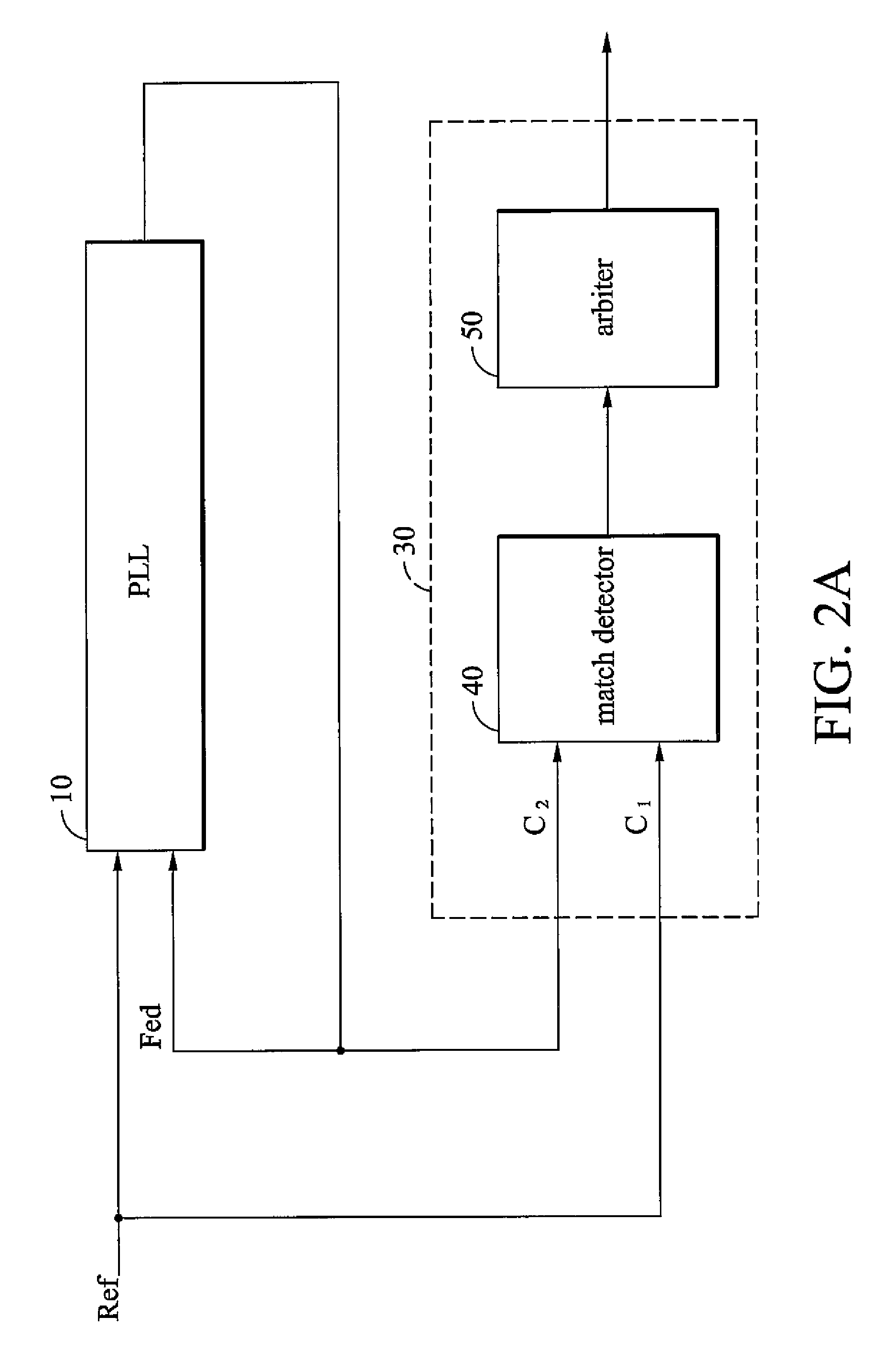
[0023]FIG. 2A is a block diagram of a phase locked-loop with a digital lock detector according to an embodiment of the invention. The phase locked-loop 10 generates a feedback clock Fed according to a reference clock Ref. The digital lock detector includes a match detector 40 and an arbiter 50. The match detector 40 detects whether a second clock C2 transitions in ...


PUM


Abstract

A digital lock detector for a phase-locked loop. The PLL generates a feedback clock according to a reference clock. The digital lock detector includes a match detector and an arbiter. When a first clock transitions, the match detector checks that whether a second clock transitions in a predetermined time window or not. The match detector generates a match signal if the second clock transitions in the predetermined time window. The arbiter counts a number of the successive match signals and generates a lock signal to indicate a lock state when the number exceeds a first predetermined number.

Description

BACKGROUND[0001]1. Field of the Invention[0002]The invention relates to a digital lock detector and, in particular, to a digital lock detector for a phase locked-loop (PLL).[0003]2. Description of the Related Art[0004]Clock generator is of great importance in modern synchronous systems, such as computer systems and communication equipments. Performance requirements of clock generators become more stringent with increasing operating speed of circuits. It is important to make sure that clocks are ready for logic operation. This function is known as lock detection and typically performed by a lock detector. In general, a lock detector is applied in frequency synthesizers or clock and data recovery (CDR) where using phase locked-loop. The PLL compares input reference clock with feedback clock that comes from a voltage controlled oscillator (VCO) . Usually, there is a variable divider between VCO and feedback clock. Once VCO's frequency enters a predetermined lock-in range, the lock dete...

Claims


Application Information

Patent Timeline
Patent Type & Authority Patents(United States)
IPC IPC(8): H03D3/24H03L7/06H03L7/095
CPCH03L7/095
Inventor CHEN, YONGCONGXU, RAYMONDSONG, ZHEN-YULI, KEN-MING
Owner VIA TECH INC
Why Eureka
Try Eureka