Fluid distribution system for a swimming pool cleaning apparatus

a technology for distribution systems and swimming pools, which is applied in the direction of diaphragm valves, engine diaphragms, operating means/release devices of valves, etc., can solve the problems of cleaning equipment that utilizes fairly complicated and/or complex mechanisms for controlling

Inactive Publication Date: 2010-03-16
HAYWARD IND INC
View PDF86 Cites 39 Cited by
  • Summary
  • Abstract
  • Description
  • Claims
  • Application Information

AI Technical Summary

Problems solved by technology

These cleaners utilize fairly complicated and / or complex mechanisms for controlling their water surface cleaning and wall surface cleaning operations.

Method used


Image

  • Fluid distribution system for a swimming pool cleaning apparatus
  • Fluid distribution system for a swimming pool cleaning apparatus
  • Fluid distribution system for a swimming pool cleaning apparatus

Examples


first embodiment

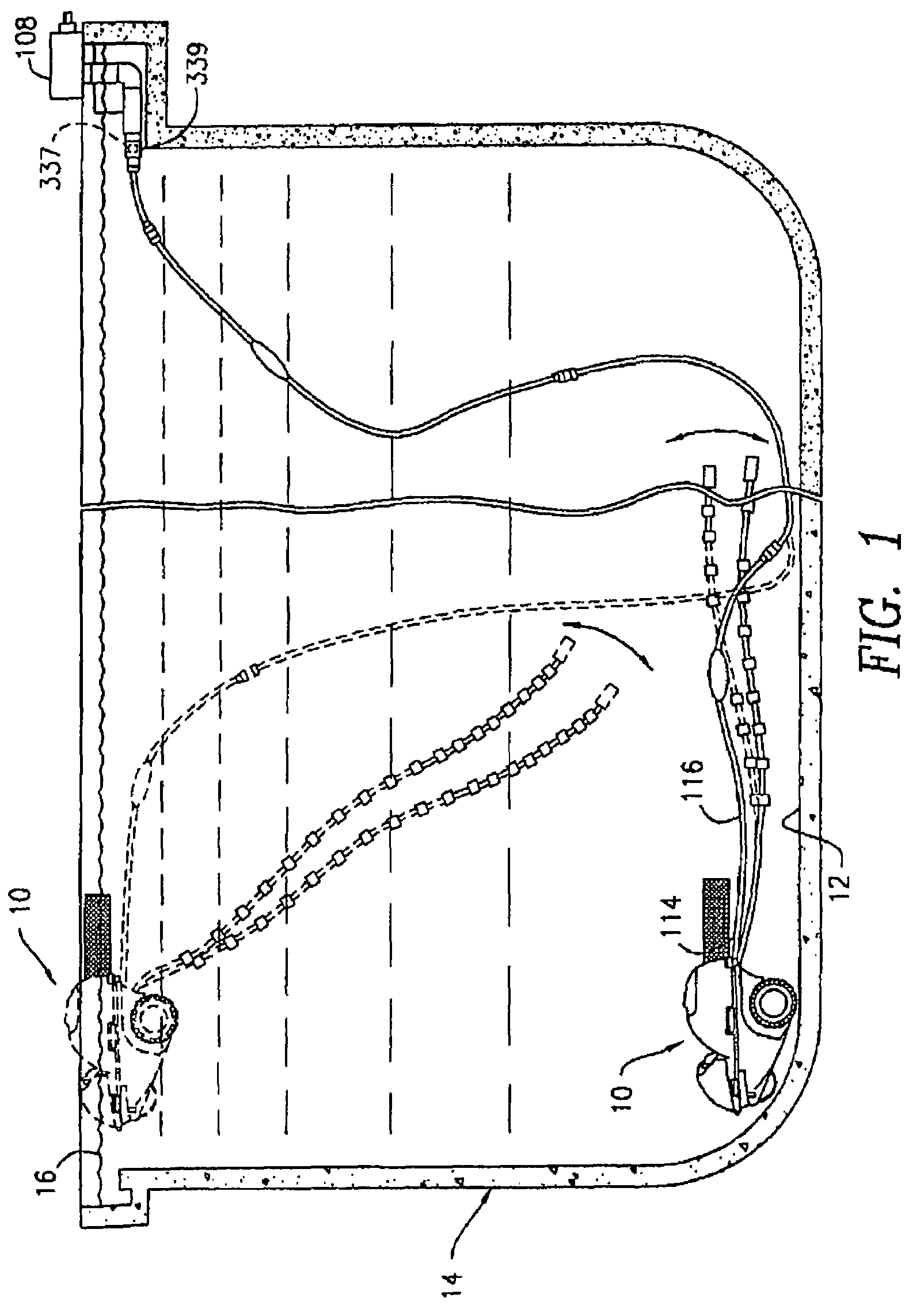
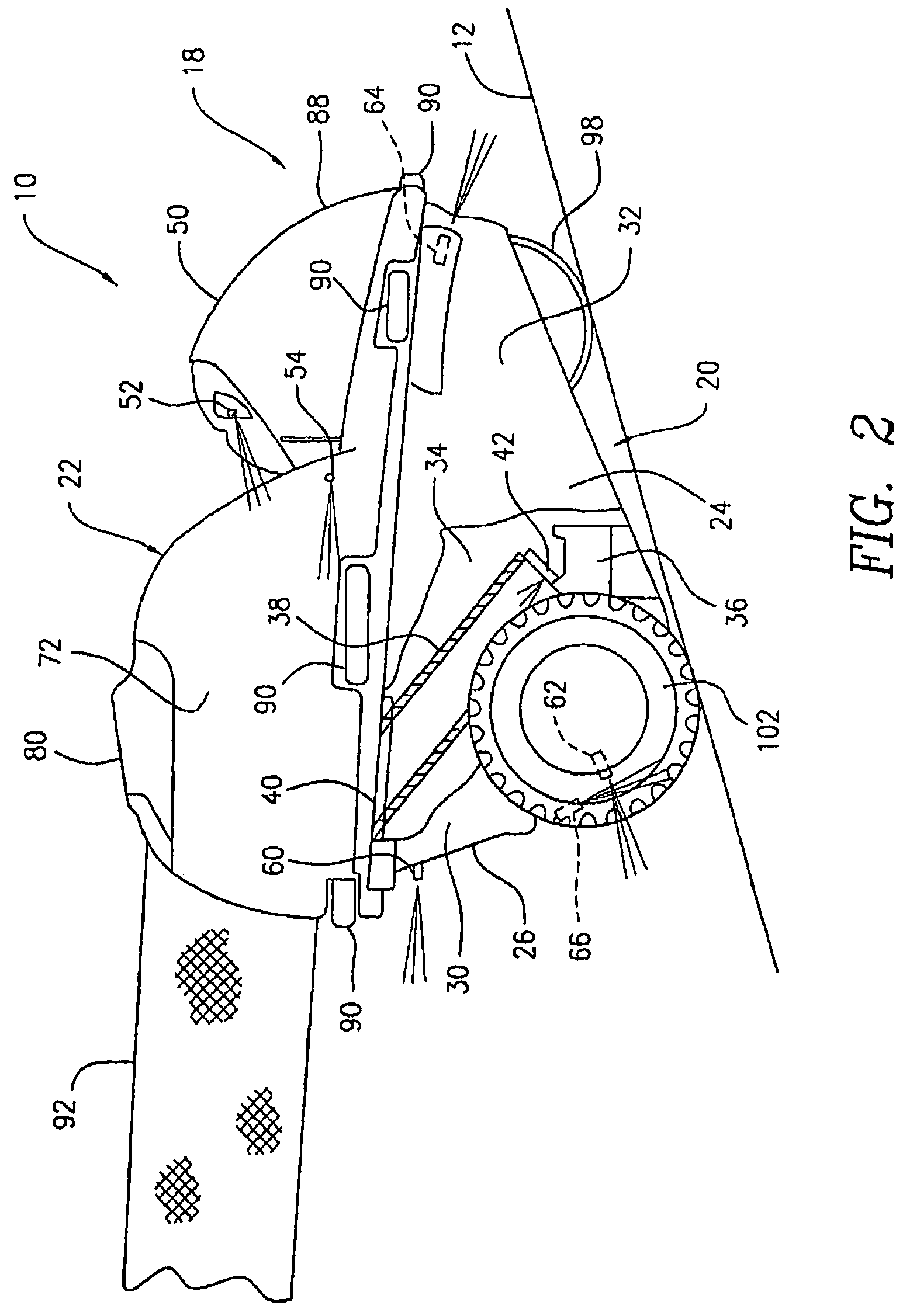
[0053]Referring initially to FIGS. 1, 2 and 2A, there is shown a positive pressure swimming pool cleaner 10 constructed in accordance with the present invention. Briefly, the cleaner 10 is adapted to operate in a manner similar to that of the cleaners disclosed in U.S. Pat. Nos. 6,090,219 and 6,365,039 and International Patent Publication No. WO 99 / 33582 (i.e., International Patent Application No. PCT / US98 / 27623), the disclosures of which are incorporated herein by reference. To facilitate consideration and discussion, the basic operation of the cleaner 10 will be discussed first, followed by a detailed discussion of its components.

[0054]With reference to FIG. 1, the cleaner 10 is adapted to clean an interior wall 12 of a swimming pool 14 and an upper surface 16 of a water contained therein. As a result, the cleaner 10, in typical operation, alternates between (1) a water surface cleaning mode (also referred to hereinafter as the “top mode”), in which it rises proximate to the water...

second embodiment

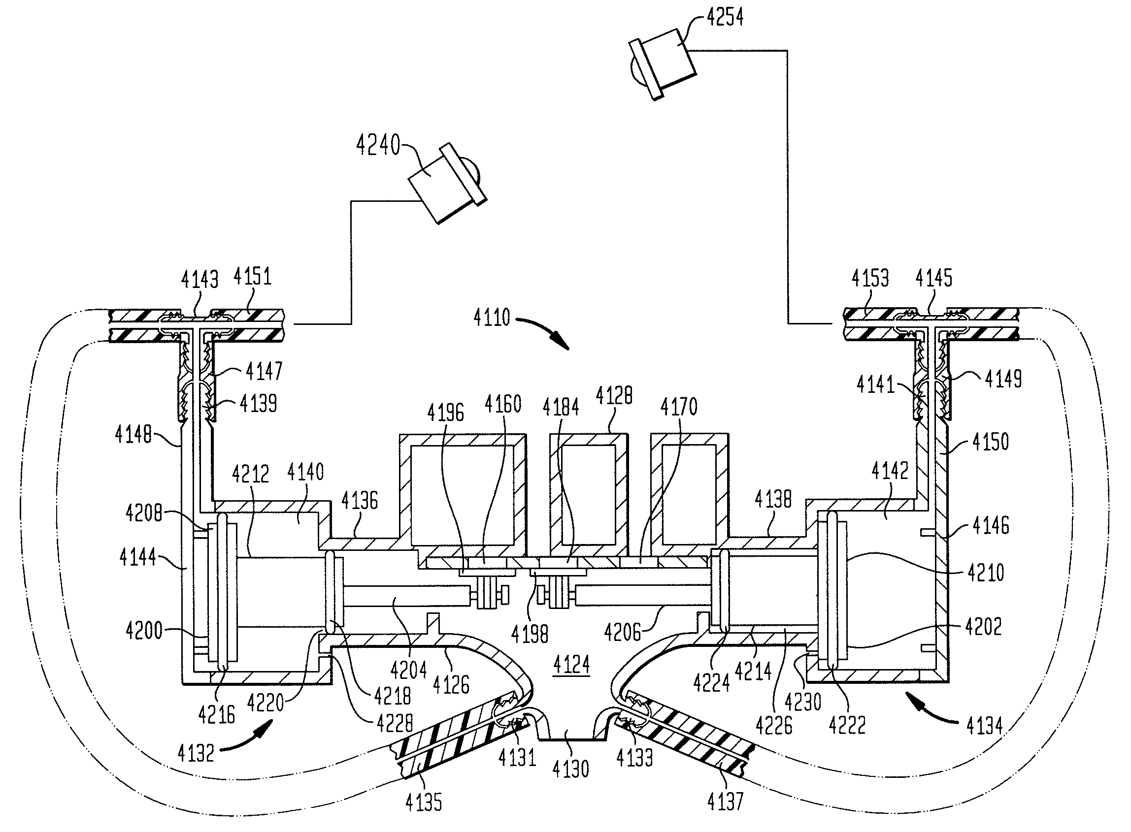
[0102]FIGS. 17-21C depict the present invention. Elements illustrated in FIGS. 17-21C, which correspond, either identically or substantially, to the elements described above with respect to the embodiment of FIGS. 1-16B, have been designated by corresponding reference numerals increased by one thousand. Unless otherwise stated, the embodiment of FIGS. 17-21C is constructed and assembled and operates in the same basic manner as the embodiment of FIGS. 1-16B.

[0103]FIGS. 17 and 18 show a pressure-type swimming pool cleaner 1010 constructed in accordance with the second embodiment of the present invention. While the cleaner 1010 is adapted for bottom mode and spin-out mode operations, it does not have a top mode (i.e., it remains proximate to an interior wall of a swimming pool throughout its operation). In such circumstances, the cleaner 1010 is devoid of the components of the embodiment of FIGS. 1-16B associated with the top mode operation. For instance, the cleaner 1010 is not provid...


PUM


Abstract

A fluid distribution system for controlling the operation of a swimming pool cleaning device includes a housing having an inlet for receiving a supply of pressurized fluid, a plurality of outlet openings and a valve chamber between the inlet and outlet openings. The housing has at least one compound cylinder having two portions with different bore diameters for slideably accommodating therein a mating stepped piston. Each portion of the compound cylinder fluidly communicates with pressurized water in the valve chamber via associated fluid pathways. The larger cylinder is vented by a relief valve actuated by a fluid driven cam that periodically opens and closes the relief valve. When the relief valve is closed, the pressure within the large cylinder pushes the piston to a first position which effects the opened / closed status of a port, e.g., allowing one of the outlets to communicate with the pressurized water in the valve chamber. When the relief valve is opened, the pressure within the larger cylinder is reduced, allowing the pressure in the smaller cylinder to push the piston to a second position which effects the opened / closed status of the port and / or opens another port to allow the pressurized fluid to be discharged through another outlet.

Description

CROSS-REFERENCE TO RELATED APPLICATIONS[0001]The present application is a continuation-in-part of U.S. patent application Ser. No. 10 / 282,223 filed Oct. 25, 2002 now U.S. Pat. No. 7,318,448, which claims the benefit under 35 U.S.C. § 119(e) of U.S. Provisional Patent App. No. 60 / 335,288, filed Nov. 30, 2001 the contents of both of which are hereby incorporated by reference in their entirety for all purposes.FIELD OF THE INVENTION[0002]The present invention relates to swimming pool cleaning apparatus and components useful in connection therewith.BACKGROUND OF THE INVENTION[0003]U.S. Pat. Nos. 6,090,219 and 6,365,039 and International Patent Publication No. WO 99 / 33582 disclose swimming pool cleaners adapted to rise proximate to a water surface of a pool for removing floating debris therefrom and to descend proximate to a wall surface of the pool for removing debris therefrom (see also U.S. Pat. Nos. 6,039,886 and 6,387,250 and International Patent Publication No. WO 99 / 34077). These ...

Claims


Application Information

Patent Timeline
Patent Type & Authority Patents(United States)
IPC IPC(8): F16K11/10
CPCE04H4/1654F16K11/20E04H4/1681Y10T137/87893Y10T137/86413
Inventor GRIFFIN, RONALDDYE, G. FRANKFLEISCHER, ERIC C.WILLIS, DENNISHARDY, DAVID
Owner HAYWARD IND INC
Why Eureka
Try Eureka