
Tire chain tightening apparatus

a technology of tightening apparatus and tire chain, which is applied in the direction of vehicle components, transportation and packaging, non-skid devices, etc., can solve the problems of difficult application, tire size and tire size variation, and loose fitting tire chain is often less effective, etc., to achieve tightening or loosening of tension in the arms, the effect of increasing or decreasing the length of the arm

Inactive Publication Date: 2010-03-16
LYNN ANTHONY
View PDF9 Cites 2 Cited by
  • Summary
  • Abstract
  • Description
  • Claims
  • Application Information

AI Technical Summary

Benefits of technology

"The present invention is an apparatus used for tightening tire chains. It includes an outer portion and an inner portion with a plurality of arms that secure to the inner portion and extend through corresponding apertures in the outer portion. The arms have a first end that attaches to the inner portion and a second end that attaches to the tire chain. The inner portion also has clamps that adjust the length of the arms relative to the tire. A bar / rod connects the outer and inner portions, and the distance between them controls the tension in the arms. The apparatus is positioned in the center of the tire and the arms attach to the tire chain. The invention allows for easy adjustment of arm length and tension in the arms by rotating a handle."

Problems solved by technology

A drawback of conventional tire chains is that they are often difficult to apply, especially if the tire chain fits snugly around a tire.
However, a loose fitting tire chain is often less effective.
Furthermore, tire sizes often vary and one set of tire chains may not be suitable for certain tire sizes.
However, depending upon the fit of the tire chains around the tire, these devices may also be very difficult to apply.
Furthermore, these devices have a very limited adjustment range.

Method used


Image

  • Tire chain tightening apparatus
  • Tire chain tightening apparatus
  • Tire chain tightening apparatus

Examples


Embodiment Construction

[0015]The present invention relates to an apparatus used for tightening tire chains which are attached to a tire. The present invention is depicted being configured for use with automobile tire chains. However, the present invention can be easily adapted for use with a variety of different tire chain sizes and can be used on a variety of different wheeled vehicles. In addition, the present invention can be adapted to be a stand-alone device or can be integral to the tire chain.

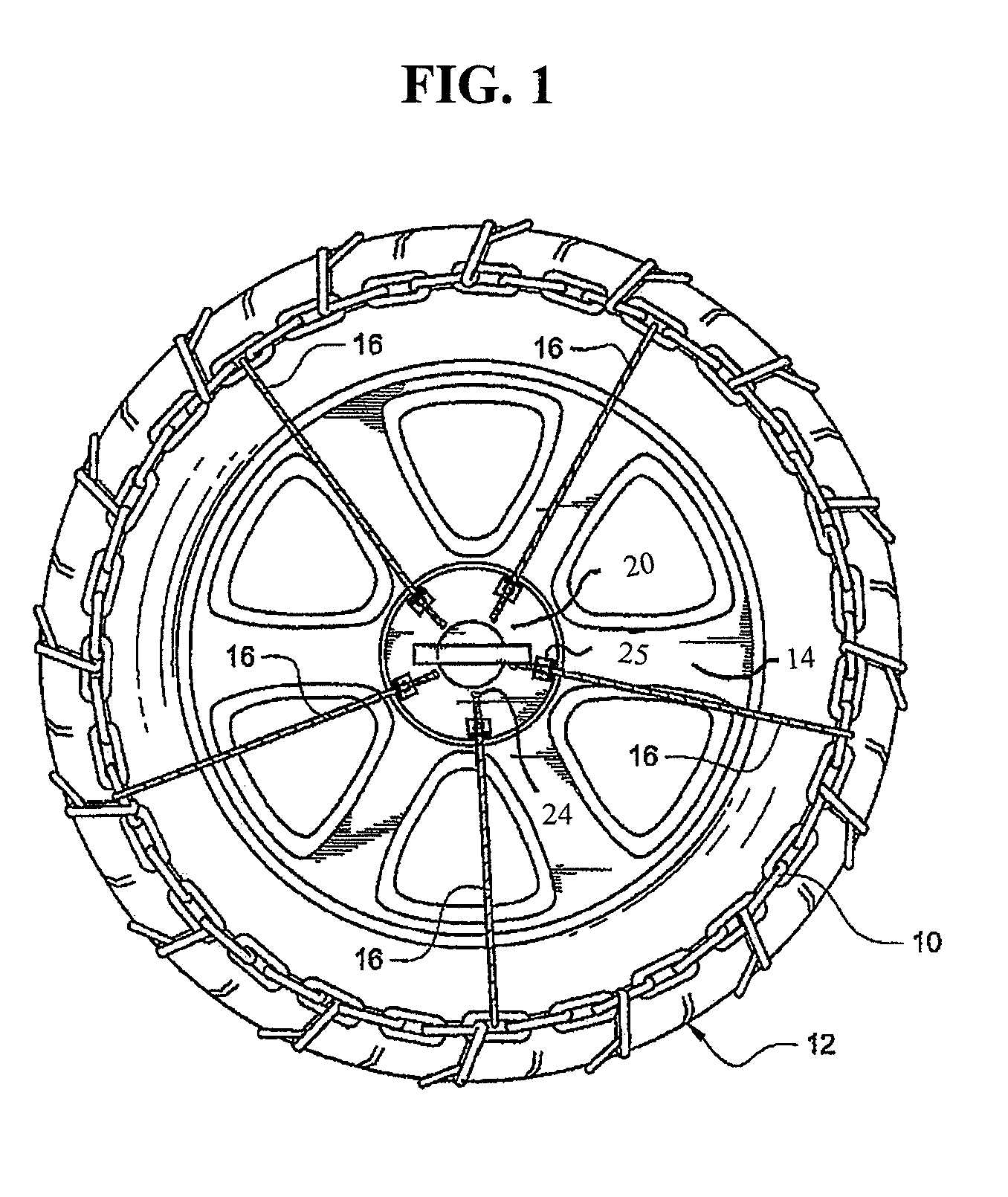
[0016]As shown in FIG. 1, one embodiment of the present invention is depicted attached to a tire chain 10 which is coupled to an automobile tire 12. The present invention is positioned over a hub cap 14 and is coupled to the tire chain via a plurality of arms 16. The arms 16 are arranged to couple circumferentially around the tire chain.

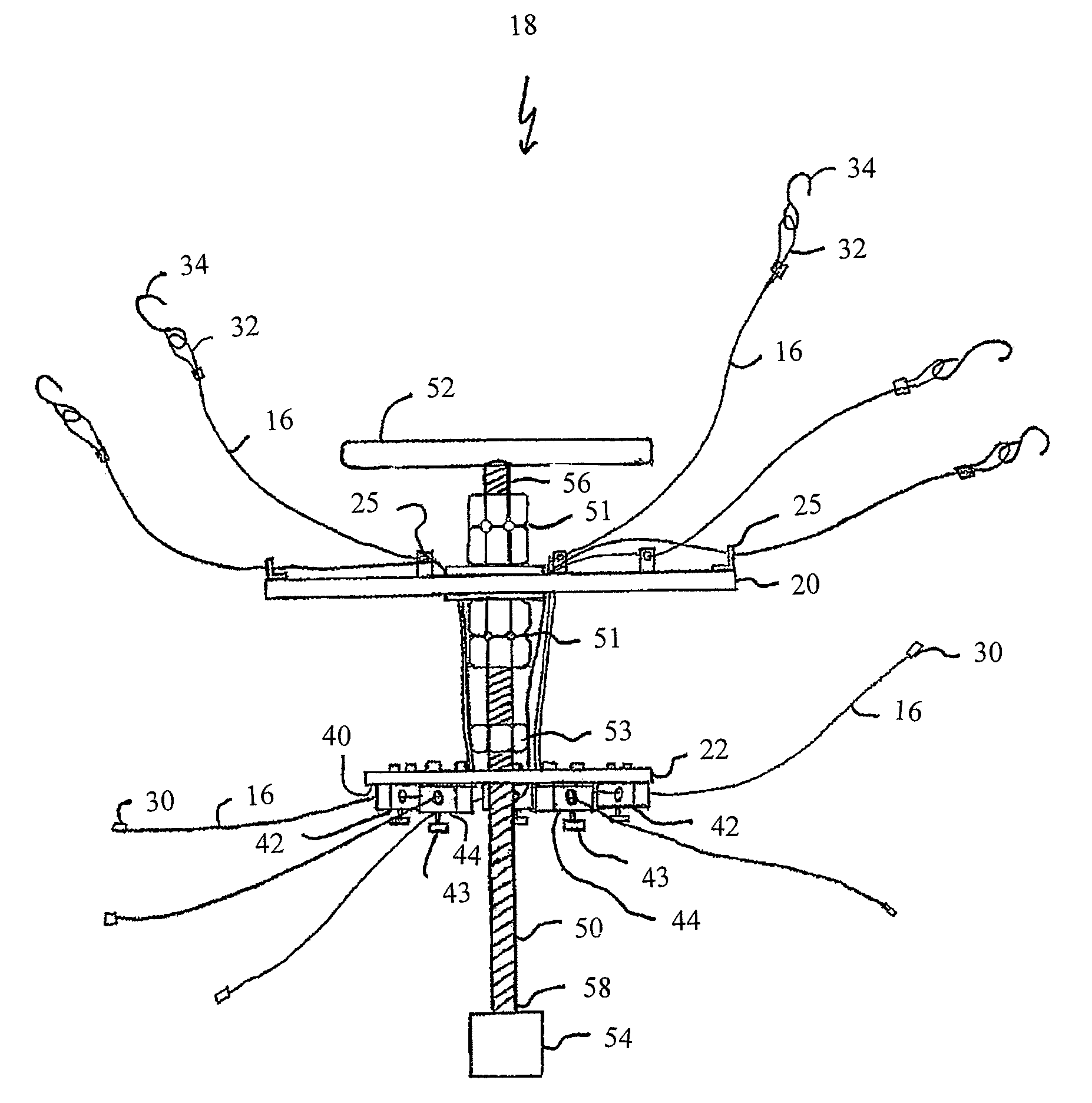
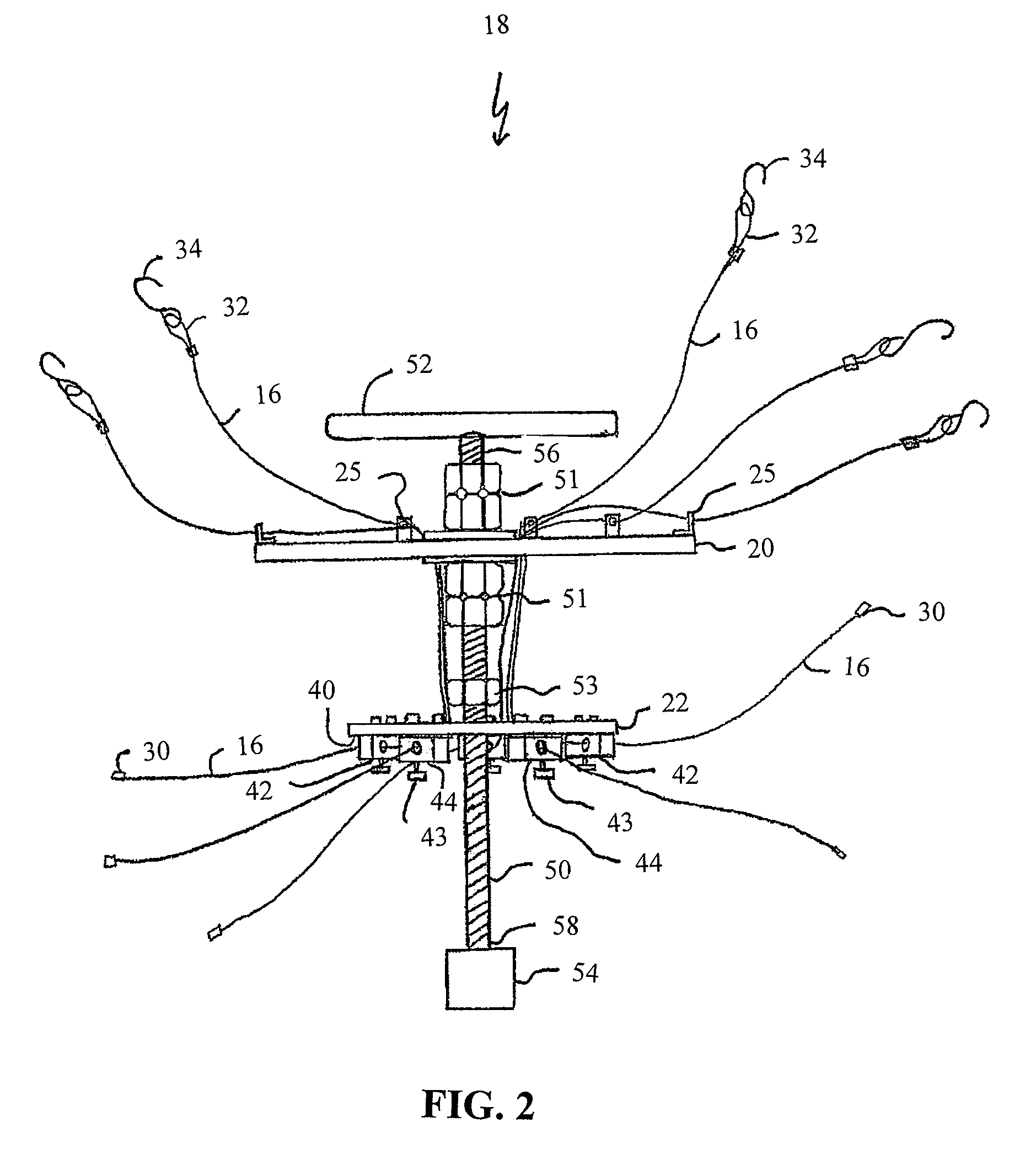
[0017]As shown in FIGS. 2, 3, and 4, one embodiment of the present invention 18 includes an outer portion 20 and an inner portion 22. As depicted in these figures, the outer 20...


PUM


Abstract

The present invention relates to an apparatus used for tightening tire chains. One embodiment of the present invention includes an outer portion and an inner portion. The outer and inner portions have a plurality of first and second apertures, respectively. A plurality of arms are secured onto the inner portion and extend through the second aperture and then through the first apertures. The arms have a first end which is adapted to be secured onto the inner portion, and a second end which is adapted to secure to a tire chain. A bar variably couples the outer portion and the inner portion. The distance between the outer and inner portions adds or subtracts tension in the arm which correspondingly adds or subtracts tension in the tire chain.

Description

FIELD OF THE INVENTION[0001]The present invention relates generally to tire chains. More specifically, the present invention relates to a tightening apparatus for a tire chain.BACKGROUND OF THE INVENTION[0002]Tire chains are often wrapped around a tire to provide added traction for snow-laden roads or for off-road driving. They are used by a number of different vehicles such as passenger cars, trucks, ATVs (all terrain vehicles), tractors and motorcycles. These chains are typically comprised of chain links or wire cable arranged in two generally parallel portions with crossing portions which connect to both parallel chain portions. One common configuration for a tire chain has two parallel portions and a plurality of crossing portions which are generally perpendicular to each parallel chain portion. Once attached to a tire, the crossing chain portion runs generally across the treads of a tire and provides added traction.[0003]Generally, a tire chain is applied circumferentially arou...

Claims


Application Information

Patent Timeline
Patent Type & Authority Patents(United States)
IPC IPC(8): B60C27/10
CPCB60C27/10
Inventor LYNN, ANTHONY
Owner LYNN ANTHONY
Learn More