

Intake apparatus of internal combustion engine
a technology of internal combustion engine and intake apparatus, which is applied in the direction of combustion engine, combustion-air/fuel-air treatment, charge feed system, etc., can solve the problems of increasing the size of the component(s) constituting the intake passage, difficult to secure the amount of air required in the high engine speed region of the internal combustion engine, and difficult to improve the intake volumetric efficiency over the entire region. , to achieve the effect of correct intake performance and compact siz
- Summary
- Abstract
- Description
- Claims
- Application Information
AI Technical Summary
Benefits of technology
Problems solved by technology
Method used
Image

Examples
first embodiment
[0041] Hereinafter, a first embodiment of the present invention will be described with reference to FIGS. 1-5. In the present embodiment, a 4-cylinder gasoline engine installed in a vehicle is shown as an example of the internal combustion engine. The number of cylinders, however, is not particularly restricted, and it may be a diesel engine.
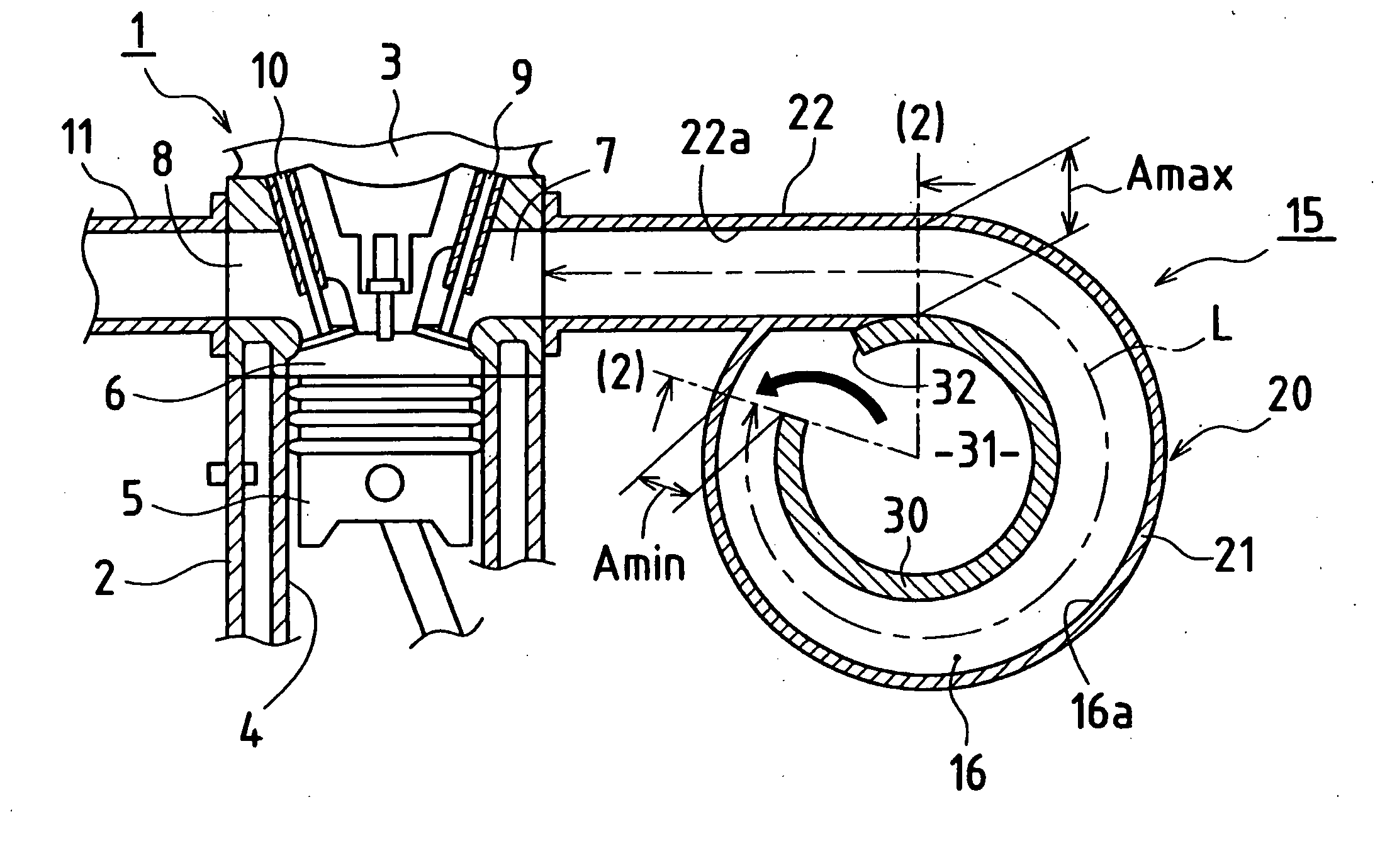
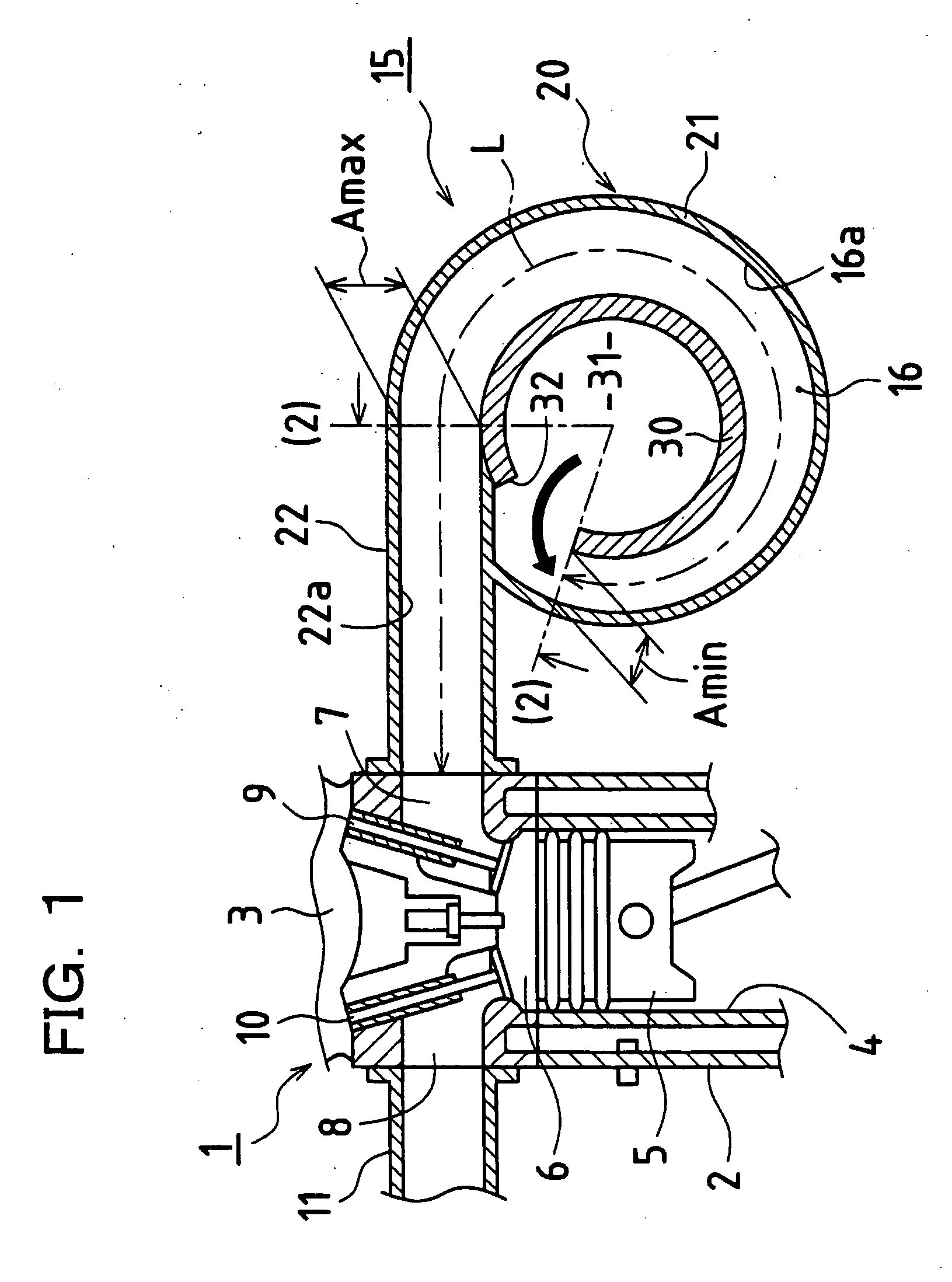
[0042] As shown in FIG. 1, the engine 1 has a cylinder block 2 and a cylinder head 3.
[0043] Cylinder block 2 is provided with a plurality of (in this case, four) cylinders 4. Each cylinder 4 has a piston 5 inserted therein, which performs a reciprocating motion. In each cylinder 4, the space partitioned by the upper end of piston 5 and cylinder head 3 constitutes a combustion chamber 6.
[0044] Cylinder head 3 has an intake port 7 and an exhaust port 8 provided corresponding to combustion chamber 6. Intake port 7 and exhaust port 8 have inner-side openings (on the side of combustion chamber 6) opened / closed by an intake valve 9 and an exhaust v...
second embodiment
[0069]FIGS. 7-10 show a second embodiment of the present invention. In the present embodiment, inner tube 30 is provided with outer peripheral grooves 16b on its outer periphery that open outward in the radial direction.
[0070] Specifically, as shown in FIG. 9, inner tube 30 has an approximately C-shape as seen from the side face, and on its outer peripheral surface, outer collars 33a and 33b are provided at the respective ends. The collars extend outward in the radial direction. The region between outer collars 33a and 33b is provided with three partition walls 33c extending outward in the radial direction. Two outer collars 33a, 33b and three partition walls 33c constitute four outer peripheral grooves 16b. Outer peripheral groove 16b of inner tube 30 and inner peripheral groove 16a of outer tube 20 together form a tubular space, which constitutes variable intake passage 16.
[0071] Disconnected portion 32 of inner tube 30 serves as the air introducing portion through which the air...
third embodiment
[0073]FIGS. 11-13 show a third embodiment of the present invention. In the present embodiment, opposite to the case of the second embodiment described above, it is configured such that outer peripheral groove 16b of inner tube 30 has a groove depth that gradually increases from the upstream side (Bmin) toward the downstream side (Bmax) in the air introducing direction, while inner peripheral groove 16a of outer tube 20 has a uniform groove depth A. In this case as well, the cross section of variable intake passage 16 gradually increases from the upstream side to the downstream side in the air introducing direction.
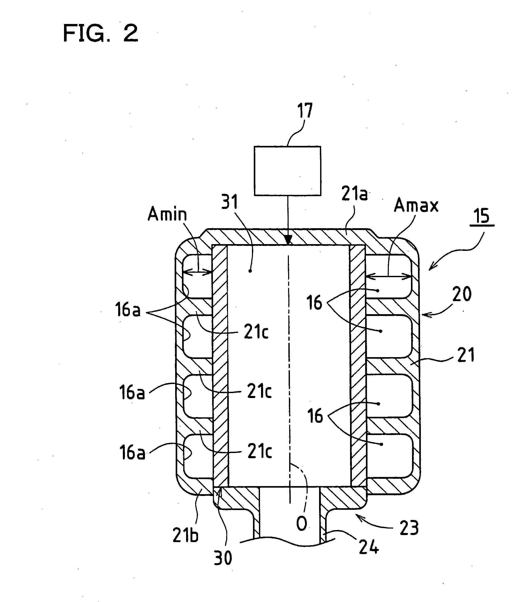
[0074] In any of the embodiments described above, intake apparatus 15 may be formed with variable intake passages 16 that are made of separate tubes independent from each other, although not shown. The number of the tubes corresponds to the number of cylinders of engine 1, and the tubes are connected together to form intake apparatus 15. For example, to form the tube cons...
PUM
 Abstract
Description
Claims
Application Information