Method and device for controlling drilling fluid pressure

a technology of fluid pressure and pressure control, which is applied in the direction of drilling pipes, well accessories, sealing/packing, etc., can solve the problems of difficult monitoring of volumetric flow in the borehole, and achieve the effect of reducing the weight of the riser and being easy to observ

Inactive Publication Date: 2010-03-16
ENHANCED DRILLING
View PDF19 Cites 53 Cited by
  • Summary
  • Abstract
  • Description
  • Claims
  • Application Information

AI Technical Summary

Problems solved by technology

When using such teachings according to these patents, it is difficult to monitor the volumetric flow in the borehole, as the annulus above the drilling fluid in the liner, or alternatively riser, is filled with gas, typically air.

Method used


Image

  • Method and device for controlling drilling fluid pressure
  • Method and device for controlling drilling fluid pressure
  • Method and device for controlling drilling fluid pressure

Examples


Embodiment Construction

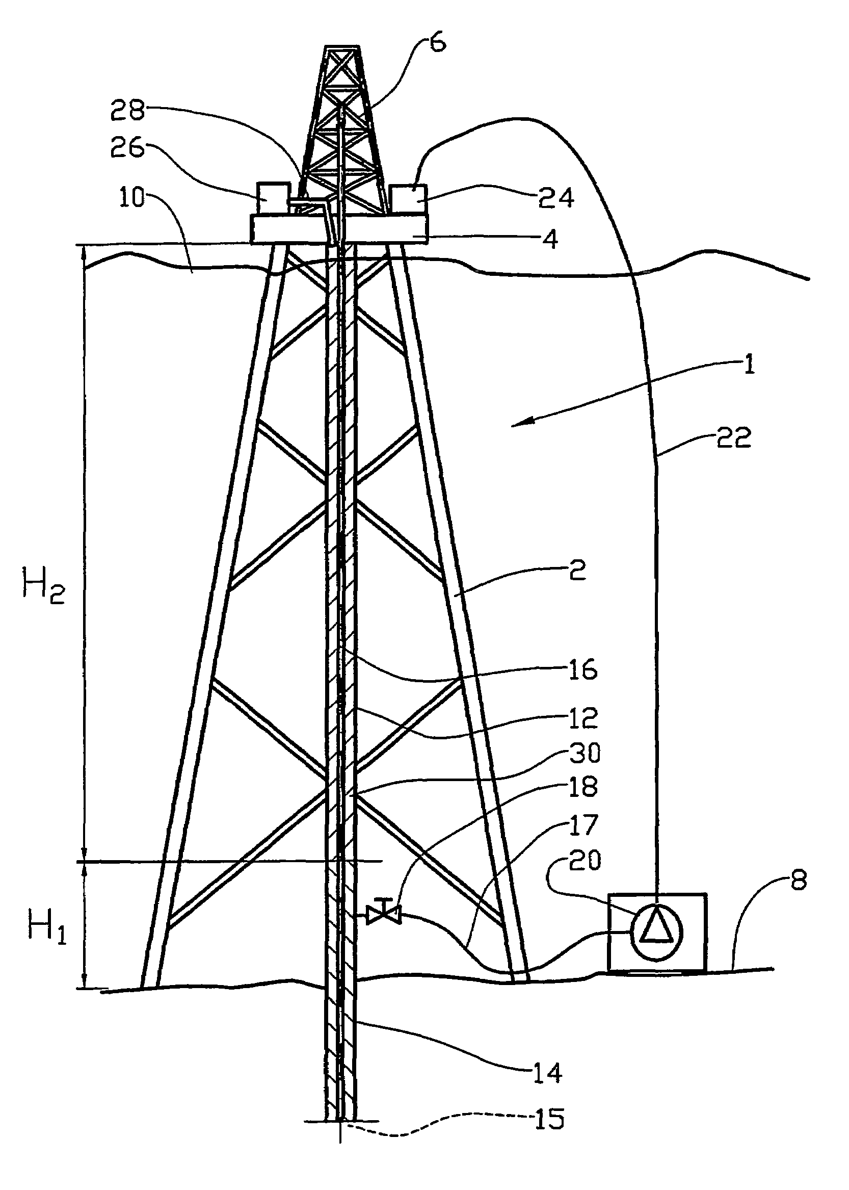
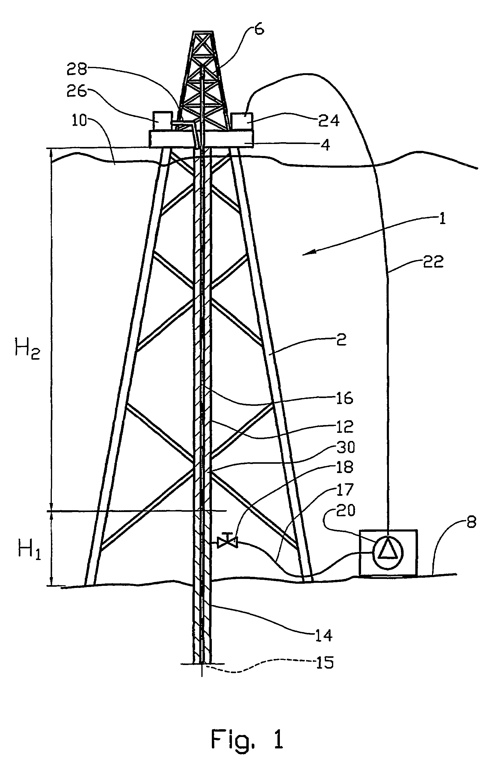
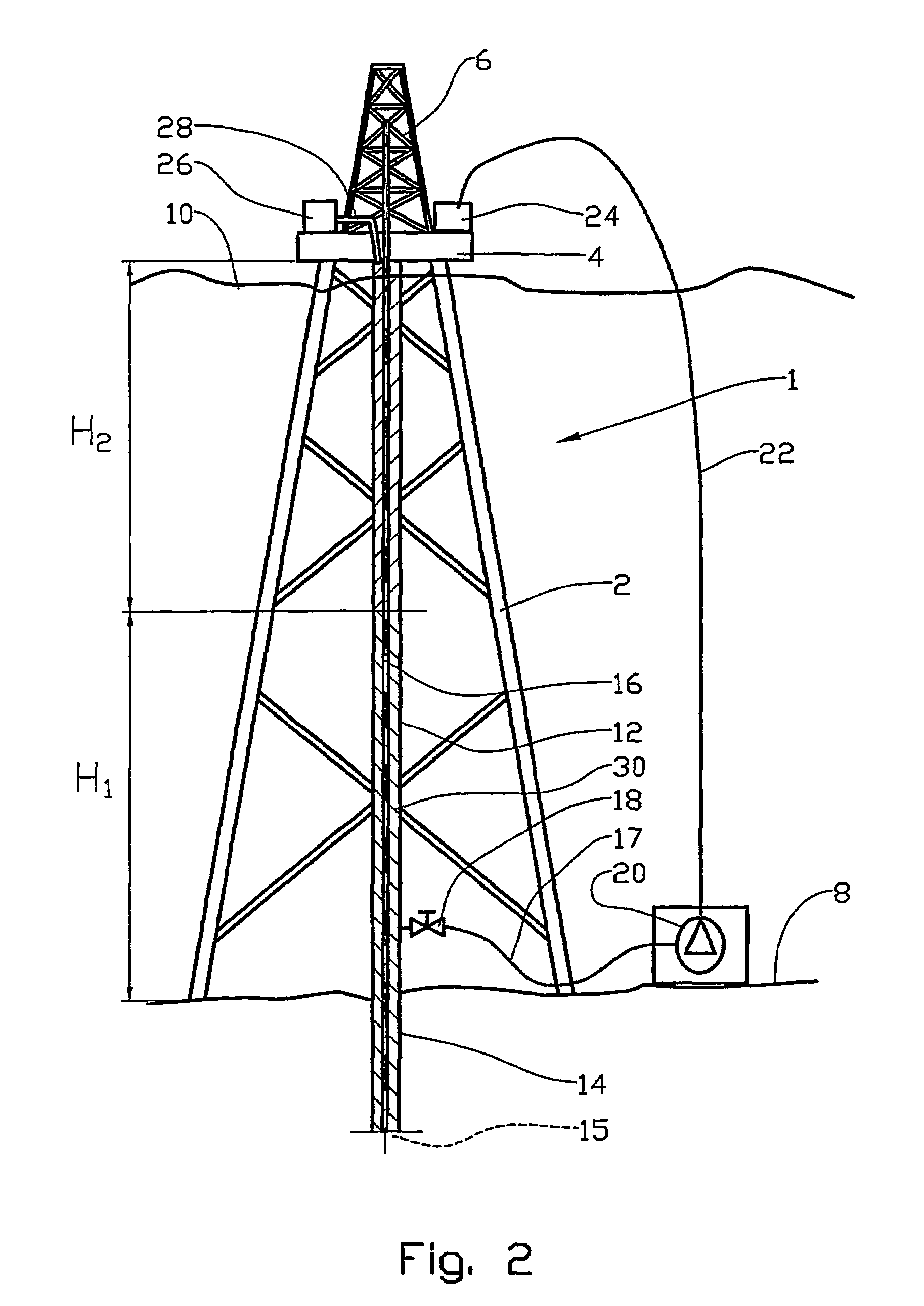
[0012]As will be described in greater detail below, with the physics being briefly discussed here, referring to FIGS. 1 and 2, when drilling from fixed platforms (drilling devices), a conductor is first driven into the seabed. When drilling a borehole 15 from a fixed drilling device, drilling fluid is pumped through a drill string 16 down to a drilling tool. The drilling fluid serves several purposes, of which one is to transport drill cuttings out of the borehole. Efficient transport of drill cuttings is conditional on the drilling fluid being relatively viscous. The drilling fluid flows back through the annulus 30 between the borehole wall, the liner 14 mentioned above and the drill string 16, and up to the drilling rig, where the drilling fluid is treated and conditioned before being pumped back down to the borehole. In many cases, this will result in a head of pressure that is undesirable.

[0013]By coupling a pump 20 to the liner 14 near the seabed, the returning drilling fluid c...


PUM


Abstract

A method of reducing drilling fluid pressure during subsea drilling, where drilling fluid is pumped down into a borehole and then flows back to a drilling rig via the lined and / or unlined sections of the borehole and a liner, wherein the drilling fluid pressure is controlled by pumping drilling fluid out of the liner at the seabed, and where the liner annulus above the drilling fluid is filled with a riser fluid having a density different from that of the drilling fluid.

Description

CROSS-REFERENCE TO RELATED PATENT APPLICATIONS[0001]This Application is a national stage entry of application PCT / NO2004 / 000359, filed on Nov. 24, 2004, the contents of which are incorporated herein by reference in their entirety. Norway priority Patent Application 20035257, filed on Nov. 27, 2003, from which the aforementioned PCT application claims priority, is likewise incorporated herein by reference in its entirety. Applicant claims priority to the aforementioned Norwegian application.BACKGROUND OF THE INVENTION[0002]During drilling operations (e.g. for petroleum production), the pressure head of drilling fluid present in a borehole and up to a platform, may cause the liquid pressure in the lower portion of the borehole to become too high.[0003]Excessive drilling fluid pressures may result in the drilling fluid causing undesirable damage to the formation being drilled (e.g. through drilling fluid penetrating into the formation).[0004]The formation may also include special geolo...

Claims


Application Information

Patent Timeline
Patent Type & Authority Patents(United States)
IPC IPC(8): E21B29/12E21B1/12E21B21/00
CPCE21B21/001E21B21/08E21B2021/006E21B21/085
Inventor STAVE, ROGER
Owner ENHANCED DRILLING
Why Eureka
Try Eureka