Aerosol spray texture apparatus for a particulate containing material

Active Publication Date: 2010-03-16
PPG ARCHITECTURAL FINISHES INC
View PDF23 Cites 32 Cited by
  • Summary
  • Abstract
  • Description
  • Claims
  • Application Information

AI Technical Summary

Benefits of technology

[0021]The present invention may be embodied as a texturing system for applying texture material to a surface. The texturing system comprises a container, a valve assembly, texture material, and propellant material. The container assembly defines a product chamber. The valve assembly is mounted to the container assembly and is operable in closed and open configurations. The texture material comprises a coating portion and a particulate portion and is disposed within the product chamber. The particulate portion comprises urethane particles. The propellant material is disposed within the product chamber and is substantially inert to the urethane particles. Operation of the valve assembly in the open configuration allows the propellant material to force the texture material from the product chamber and onto the surface.

Problems solved by technology

However, such prior art aerosol spray texture devices have not been properly adapted to deliver a texture having particulate matter therein to provide the rougher texture.

Method used


Image

  • Aerosol spray texture apparatus for a particulate containing material
  • Aerosol spray texture apparatus for a particulate containing material
  • Aerosol spray texture apparatus for a particulate containing material

Examples


Embodiment Construction

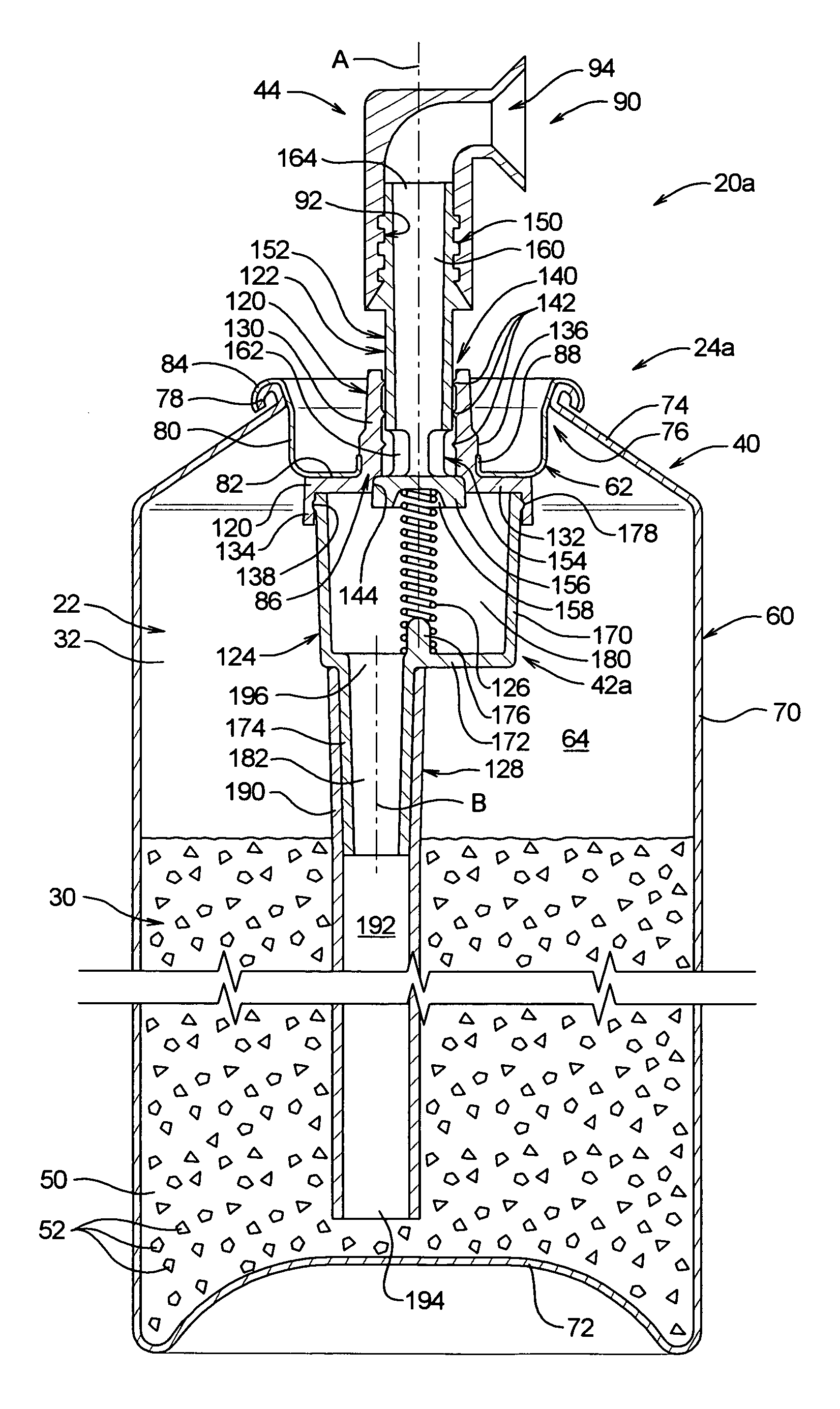
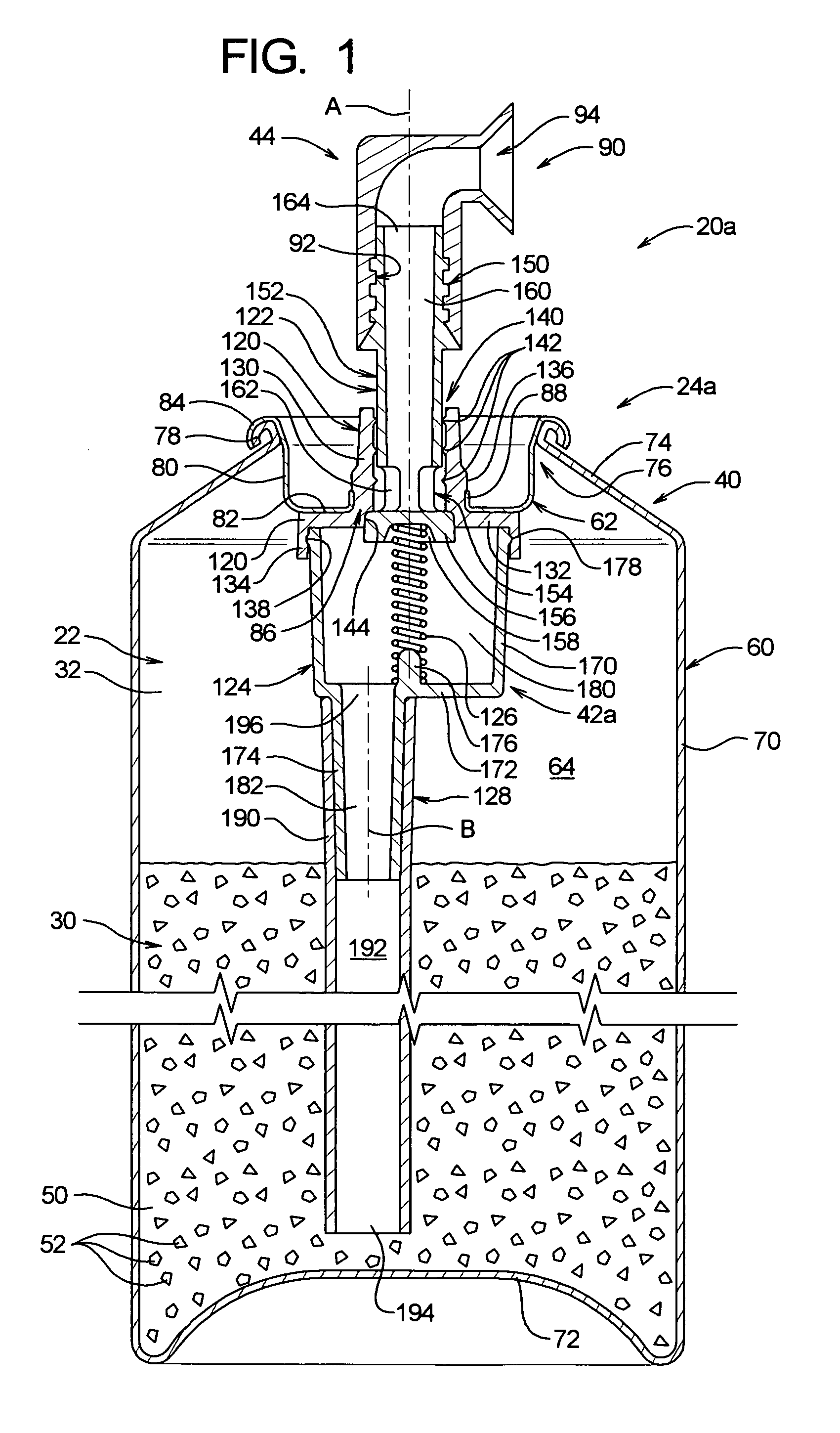
[0024]Depicted in FIGS. 1 and 2 of the drawing are first and second examples of an aerosol acoustic texturing systems 20a and 20b constructed in accordance with, and embodying, the principles of the present invention. In the following discussion and the drawing, the appendices “a” and “b” will be used to refer to features unique to the first and second example texturing systems 20a and 20b, respectively.

[0025]The example aerosol acoustic texturing systems 20a and 20b comprise a fluid system 22 and a mechanical system 24a, 24b. The fluid system 22 comprises an acoustic texture material 30 to be dispensed and a propellant material 32. The mechanical systems 24a and 24b comprise a container assembly 40, an actuator 44, and a valve assembly 42a and 42b, respectively. For clarity in FIGS. 1 and 2, the texture material 30 is shown only in the container assembly 40; as will be described in further detail below, the texture material will also forced into the valve assembly 42a, 42b and, in ...


PUM


Abstract

A texturing system for applying texture material to a surface. The texturing system comprises a container, a valve assembly, texture material, and propellant material. The container assembly defines a product chamber. The valve assembly is mounted to the container assembly and is operable in closed and open configurations. The texture material comprises a coating portion and a particulate portion and is disposed within the product chamber. The particulate portion comprises urethane particles. The propellant material is disposed within the product chamber and is substantially inert to the urethane particles. Operation of the valve assembly in the open configuration allows the propellant material to force the texture material from the product chamber and onto the surface.

Description

RELATED APPLICATIONS[0001]This application claims priority of U.S. Provisional Application Ser. No. 60 / 585,233 filed Jul. 2, 2004, the contents of which are incorporated herein by reference.FIELD OF THE INVENTION[0002]The present invention relates to a texture spraying apparatus for discharging a texture material onto a surface, and more particularly to an aerosol spray texture apparatus particularly adapted to discharge a texture material having particulate matter contained therein.BACKGROUND OF THE INVENTION[0003]Buildings are commonly comprised of a frame to which a roof, exterior walls, and interior walls and ceilings are attached. The interior walls and ceilings are commonly formed using sheets of drywall material that are attached to frame, usually by screws or nails. When the sheets of drywall are hung, small gaps are normally formed between adjacent sheets of drywall material. In addition, the fasteners are countersunk slightly but are visible.[0004]To hide the gaps and fast...

Claims


Application Information

Patent Timeline
IPC IPC(8): B65D83/00
CPCB65D83/30B65D83/48E04B1/84B65D83/752E04F21/12
Inventor GREER, JR., LESTER R.FRENCH, FLOYD R.
Owner PPG ARCHITECTURAL FINISHES INC
Why Eureka
Try Eureka