Method and apparatus for generating lift

a technology for generating equipment and lifting, applied in the field of vehicles, can solve the problems of large amount of gasflow required by ibf, usb, ebf systems affecting the flight of aircraft, etc., and disrupting the distribution of lift along the wing

Active Publication Date: 2010-03-16
THE BOEING CO
View PDF41 Cites 27 Cited by
  • Summary
  • Abstract
  • Description
  • Claims
  • Application Information

AI Technical Summary

Problems solved by technology

However, the amount of gasflow required by IBF, USB, and EBF systems can place significant demands on aircraft engines.
A larger engine, which provides inferior cruise performance, may be needed to accommodate the gas flow requirements of such systems.
Furthermore, if an engine becomes inoperable the aircraft may experience a loss of localized lift on a wing adjacent the inoperable engine thereby disrupting an even distribution of lift along the wing.

Method used


Image

  • Method and apparatus for generating lift
  • Method and apparatus for generating lift
  • Method and apparatus for generating lift

Examples


Embodiment Construction

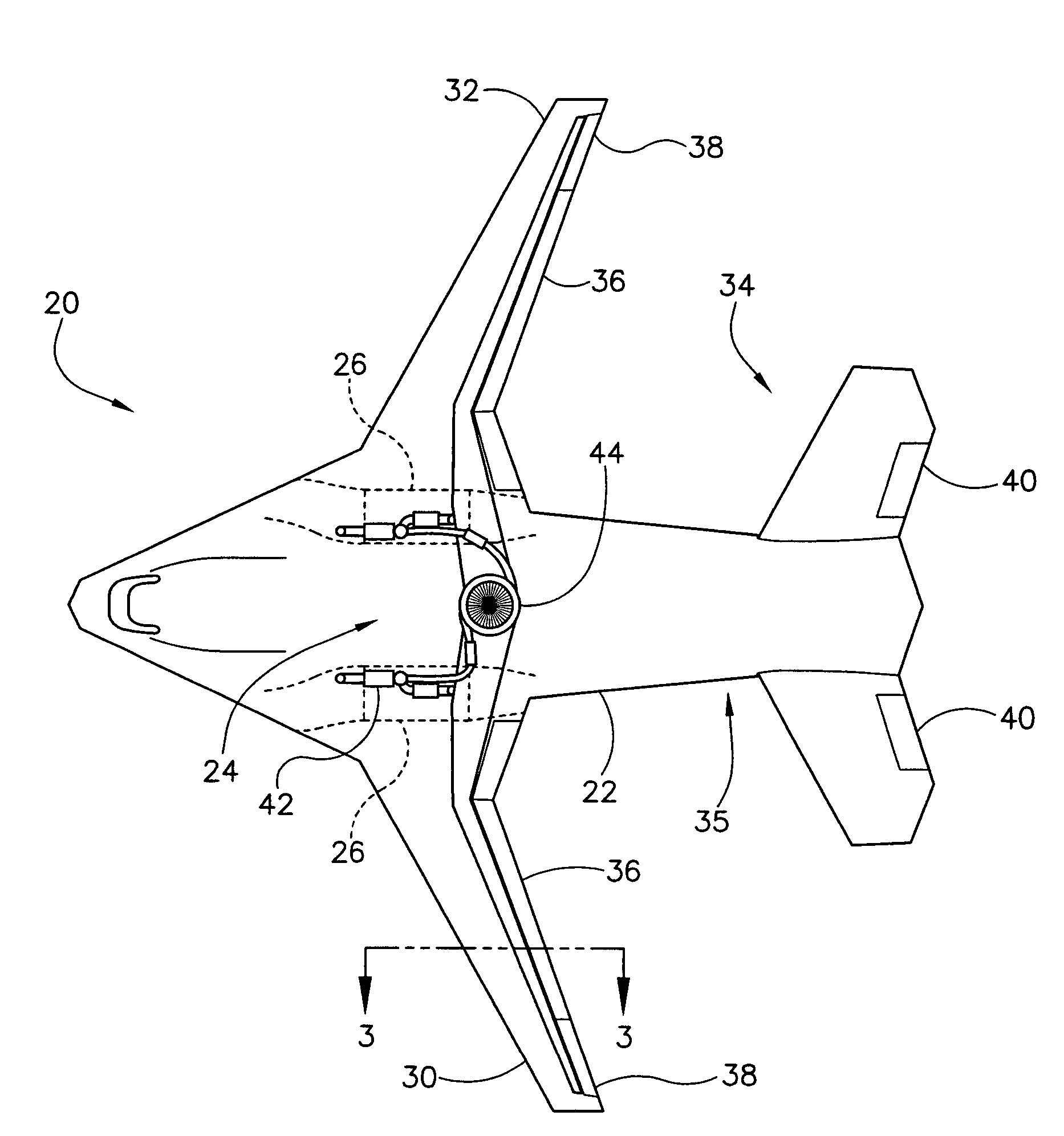
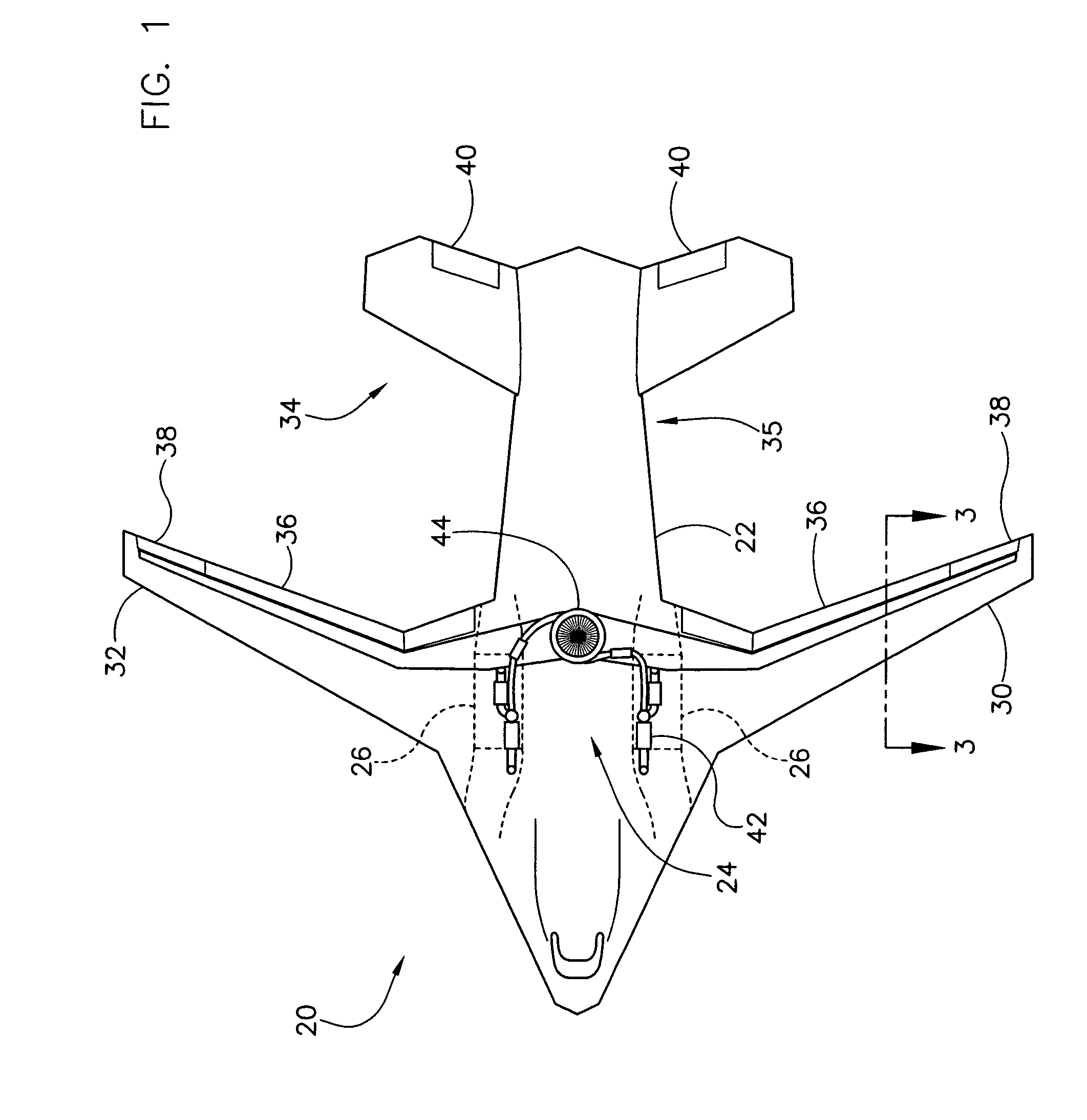
[0011]Referring now to the drawings, and more specifically to FIG. 1, an aircraft is designated in its entirety by the reference numeral 20. The aircraft 20 includes an airframe (generally designated by 22), a lift system (generally designated by 24) mounted on the airframe for generating lift for the aircraft, and two engines 26 mounted on the airframe for propelling the aircraft. The airframe 22 includes a fuselage section 28, a pair of wings 30, 32 extending laterally outward from the fuselage, and a tail assembly (generally designated by 34) extending from a rearward end (generally designated by 35) of the fuselage. Each of the wings 30, 32 and the tail assembly 34 include lifting or control surfaces. Specifically, each of the wings 30, 32 has a flap 36 and an aileron 38, and the tail assembly 34 includes elevators 40. The aircraft 20 may have other lifting or control surfaces (not shown) in addition to and / or instead of the flaps 36, the ailerons 38, and / or the elevators 40 wit...


PUM


Abstract

A method of generating lift for a vehicle including heating a flow of gas using a gas generator mounted on the vehicle that contributes no more than about ten percent of thrust used to propel the vehicle in a forward direction, and driving a lift fan using the heated gas flow to generate lift for the vehicle.

Description

BACKGROUND OF THE INVENTION[0001]The present invention relates generally to vehicles, and more specifically to a method and apparatus for generating lift for a vehicle.[0002]Some aircraft include short take-off and landing (STOL) technology to allow the aircraft to take-off from, and land on, conventionally short and / or damaged runways. STOL technology may include mechanical devices such as flaps and slats, and / or powered lifts systems such as internally blown flap (IBF), upper surface blowing (USB), externally blown flap (EBF), augmentor wing, and vectored thrust systems. Systems such as IBF, USB, and EBF often use engine bleed air or diverted exhaust gases to increase or amplify localized lift generated by the wings. However, the amount of gasflow required by IBF, USB, and EBF systems can place significant demands on aircraft engines. A larger engine, which provides inferior cruise performance, may be needed to accommodate the gas flow requirements of such systems. Furthermore, if...

Claims


Application Information

Patent Timeline
Patent Type & Authority Patents(United States)
IPC IPC(8): B64C3/50B64D27/00
CPCB64C9/18B64C9/38Y02T50/166Y02T50/44B64C2230/04Y02T50/10Y02T50/40
Inventor LAWSON, EDWARD L.DRONEY, CHRISTOPHER K.CUMMINGS, DAROLD B.
Owner THE BOEING CO
Why Eureka
Try Eureka