Electrically coupled supercharger for a gas turbine engine

a gas turbine engine and supercharger technology, applied in the direction of engines, machines/engines, mechanical equipment, etc., can solve problems such as affecting performance, and achieve the effect of eliminating mechanical clutching problems

Active Publication Date: 2009-04-07
RTX CORP
View PDF18 Cites 70 Cited by
  • Summary
  • Abstract
  • Description
  • Claims
  • Application Information

AI Technical Summary

Benefits of technology

[0007]It is an object of the present invention to provide a gas turbine engine which eliminates mechanical clutching problems.
[0008]It is a further object of the present invention to re-match the operating speed of the gas generator compressor of a gas turbine engine in order to improve the efficiency and surge margin of the compressor and to improve the transient performance of the gas turbine engine.
[0010]In accordance with the present invention, a gas turbine engine having improved transient performance and a gas generator compressor with improved efficiency and surge margin is provided. The gas turbine engine broadly comprises a spool having a turbine and a compressor mounted thereto, a first shaft and a free turbine mounted to the first shaft, and means for transferring power between the spool and the shaft.

Problems solved by technology

In the past, such engines have suffered mechanical clutching problems that detracted from their performance.

Method used


Image

  • Electrically coupled supercharger for a gas turbine engine
  • Electrically coupled supercharger for a gas turbine engine
  • Electrically coupled supercharger for a gas turbine engine

Examples


Embodiment Construction

)

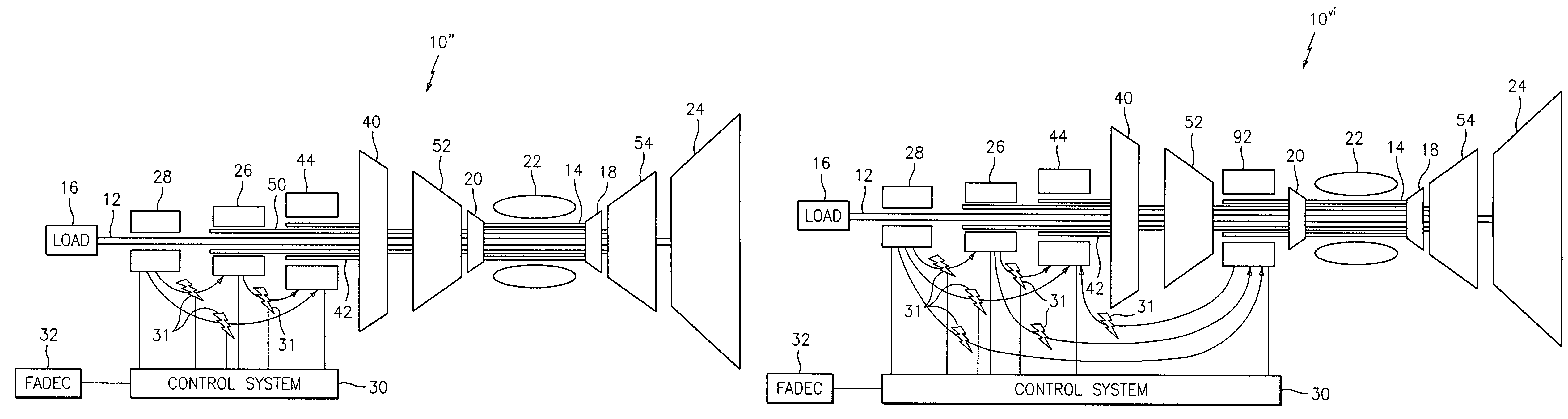
[0018]Referring now to the drawings, FIG. 1 illustrates a gas turbine engine 10, in particular a turboshaft engine, which can be used in aircraft applications, such as for driving the main rotor of a helicopter. The configuration of the gas turbine engine 10 is a two shaft engine with each shaft 12 and 14 being free to rotate independently from the other and at different speeds. In general, the speeds are significantly different between the shafts 12 and 14, e.g. a factor of 2 or more. The shaft 12 is a power output shaft which may be connected to a load 16. The shaft 14 is actually a spool to which a gas generator turbine 18 and a gas generator compressor 20 are mounted using any suitable means known in the art. If desired, the compressor 20 may be a variable geometry gas generator compressor. Intermediate the compressor 20 and the turbine 18 is a means 22 for heating the gas leaving the compressor 20 to increase the energy of the gas prior to the gas entering the turbine 18. The ...


PUM


Abstract

A gas turbine engine, in particular a turboshaft engine, includes a spool having a turbine and a gas generator compressor mounted thereto, a source of heat positioned between the turbine and the compressor, a first shaft and a free turbine mounted to the first shaft, and a control system for transferring power between the spool and the shaft. The operating speed of the gas generator compressor is re-matched in order to improve the efficiency and surge margin of the gas generator compressor and to improve the transient performance of the gas turbine engine.

Description

STATEMENT OF GOVERNMENT INTEREST[0001]The Government of the United States of America may have rights in the present invention as a result of Contract No. DAAH10-03-C-0051 awarded by the U.S. Department of the Army.BACKGROUND OF THE INVENTION[0002](1) Field of the Invention[0003]The present invention is directed to a gas turbine engine, in particular a turboshaft engine, which has particular utility in aircraft engine applications.[0004](2) Prior Art[0005]Gas turbine engines, such as turboshaft engines, are known in the art. In the past, such engines have suffered mechanical clutching problems that detracted from their performance.[0006]There is a need for a gas turbine engine which eliminates such mechanical clutching problems.SUMMARY OF THE INVENTION[0007]It is an object of the present invention to provide a gas turbine engine which eliminates mechanical clutching problems.[0008]It is a further object of the present invention to re-match the operating speed of the gas generator com...

Claims


Application Information

Patent Timeline
Patent Type & Authority Patents(United States)
IPC IPC(8): F02C3/10F02C6/00
CPCF01D15/10F02C3/10F02C3/113F02C7/36F02C9/56F05D2220/329F05D2270/101F05D2270/023
Inventor KUPRATIS, DANIEL B.
Owner RTX CORP
Why Eureka
Try Eureka