Aircraft propulsion systems

a propulsion system and aircraft technology, applied in the field of aircraft industry, can solve the problems of reducing fuel burn, too fast rotation speed of a large bladed propulsion element b>36/b> for optimum aerodynamic efficiency, and limitation of wing b>24/b> to runway clearance, so as to reduce fuel burn and weight

Active Publication Date: 2010-07-13
RTX CORP
View PDF30 Cites 67 Cited by
  • Summary
  • Abstract
  • Description
  • Claims
  • Application Information

AI Technical Summary

Benefits of technology

[0014]A primary advantage of the present arrangements is the ability to reduce fuel burn and weight by driving multiple bladed propulsion elements with a single gas generator core.

Problems solved by technology

The added thrust of a larger bladed propulsion element 36 is often negated by the weight increase, making ever-larger bladed propulsion elements 36 an unattractive alternative for reduced fuel burn.
The speed at which a large bladed propulsion element 36 rotates is also too fast for optimum aerodynamic efficiency and wing 24 to runway clearance is a limitation as well.
Although the GTF provides benefits over other high bypass ratio turbofans, the wing 24 to runway clearance ultimately limits the maximum obtainable bladed propulsion element 36 diameter.
While the above-described propulsion systems 30 provide reduced fuel burn, there are still limitations to the size of the bladed propulsion element 36 that may be driven.

Method used


Image

  • Aircraft propulsion systems
  • Aircraft propulsion systems
  • Aircraft propulsion systems

Examples


Embodiment Construction

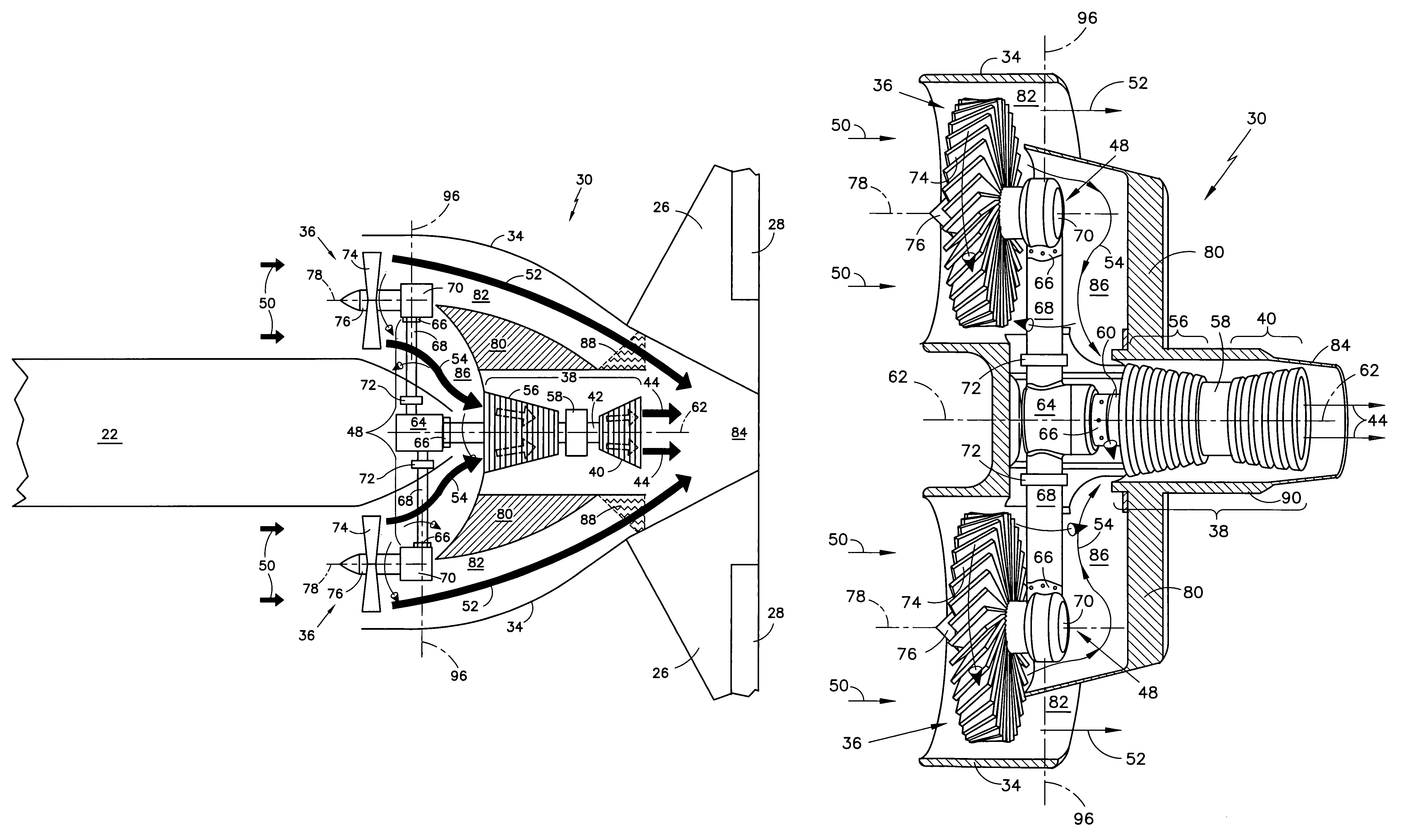
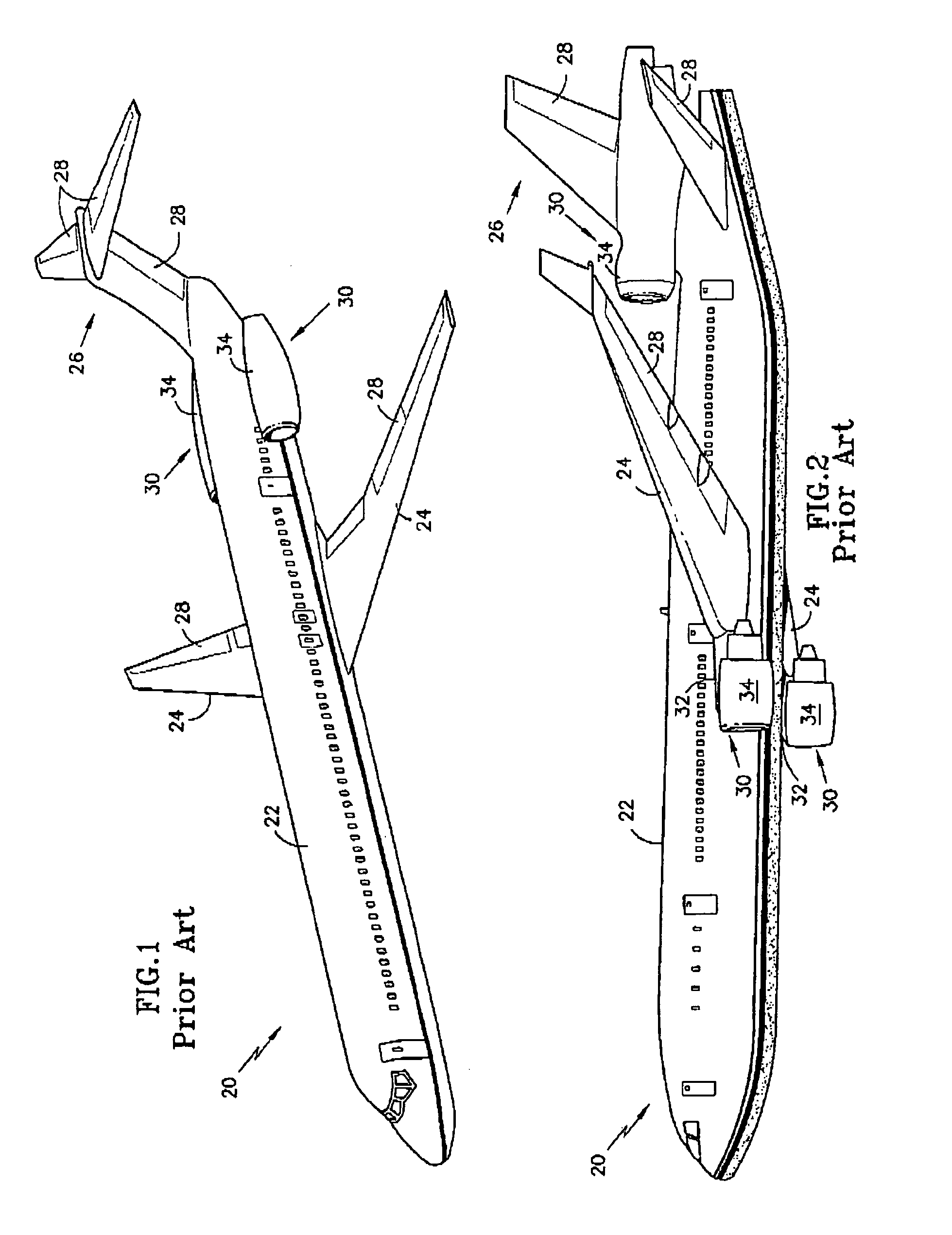
[0025]A propulsion system 30 according to an embodiment of the present invention is illustrated in FIG. 4. Those skilled in the art will recognize an airframe 20 including a central, tubular fuselage 22 for carrying passengers and cargo, wings 24 extending outwardly from the fuselage 22 for providing lift, a rear mounted tail 26 and variable surfaces 28 for controlling the airframe 20 in flight. Mounted within the fuselage 22 and beneath the tail 26 is a propulsion system 30 including a single gas generator core 38 driving multiple bladed propulsion elements 36 via a power train 48. An ambient air stream 50 is directed rearward from the bladed propulsion elements 36 as a bypass stream 52 and a core stream 54. The bypass stream 52 is used for additional thrust, while the core stream 54 is directed into the core 38.

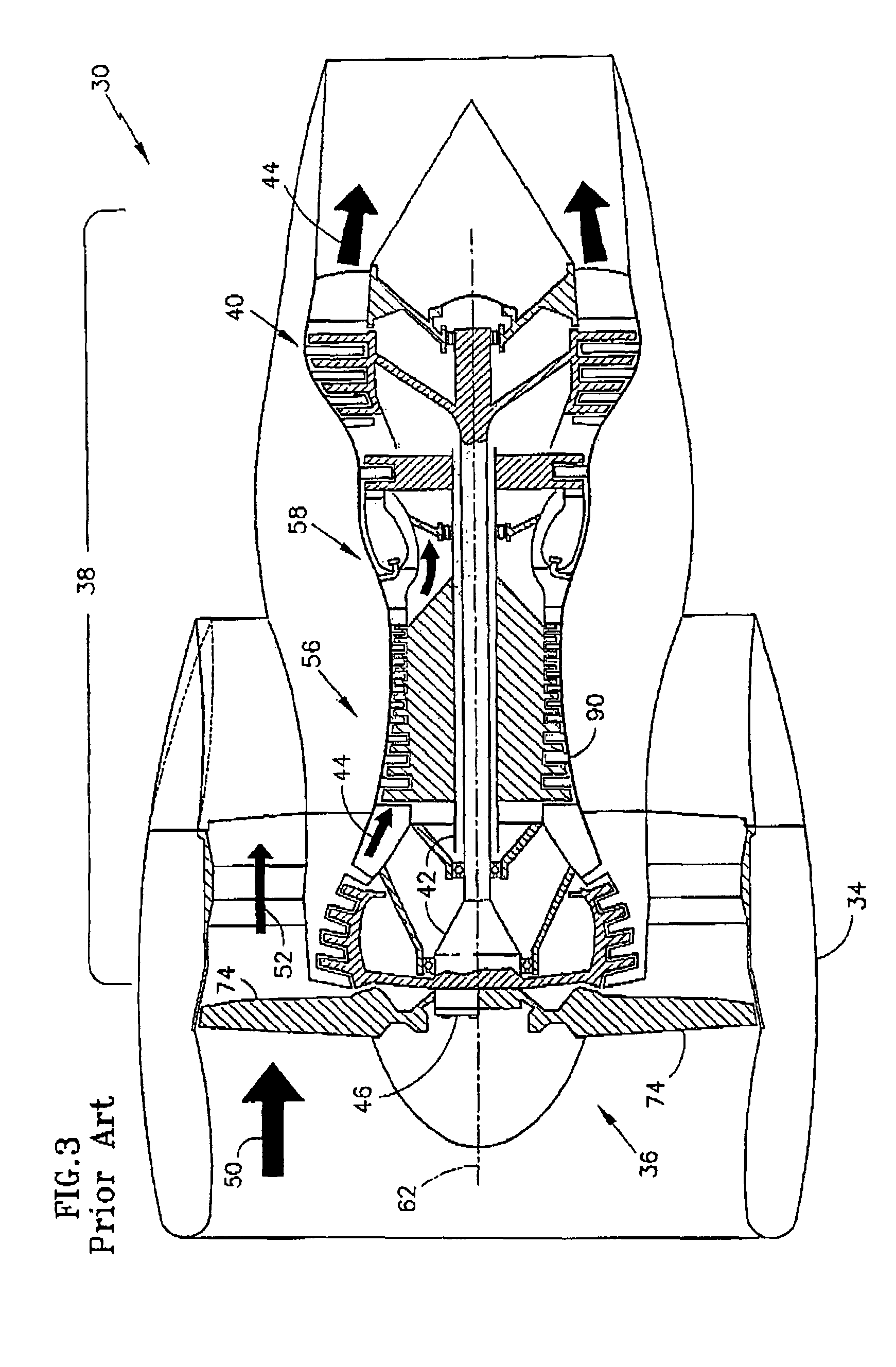
[0026]Directing your attention now to FIG. 5, further details of a present propulsion system 30 embodiment are illustrated. The gas generator core 38 includes a forward com...


PUM


Abstract

Disclosed are propulsion systems 30 providing reduced fuel burn, weight and cost. A single gas generator core 38 drives multiple bladed propulsion elements 36 with a power train 48. The core 38 has a forward compressor 56 and a rearward turbine 40 and rotates about a longitudinal core axis 62. The bladed propulsion elements 36 rotate about bladed propulsion element axes 78 that are not coaxial with the core axis 62. The bladed propulsion elements 36 discharge an ambient air stream 50 rearward as a bypass stream 52 portion and a core stream 54 portion. The core stream 54 portion is directed to the compressor 56. The propulsion systems 30 mount inside a fuselage 22 of an airframe 20 or they are suspended beneath a wing 24 via pylons 32.

Description

CROSS-REFERENCE TO RELATED APPLICATIONS[0001]This application discloses subject matter related to copending United States patent application entitled, “AIRCRAFT AIRFRAME ARCHITECTURES”, 11 / 586,175 and filed concurrently herewith, the contents of which is herein incorporated by reference.BACKGROUND OF THE INVENTION[0002](1) Field of the Invention[0003]The invention relates to the airline industry in general and more specifically to improved propulsion systems for powering aircraft airframes.[0004](2) Description of the Related Art[0005]As illustrated in FIGS. 1-2, commercial aircraft airframes 20 have a central fuselage 22 for carrying passengers and cargo, wings 24 extending outwardly from the fuselage 22 for providing lift, a rear mounted tail 26 and variable surfaces 28 for control. Typically, the airframe 22 is powered by one or more propulsion systems 30 mounted in various arrangements. The propulsion systems 30 may be mounted alongside the rear portion of the fuselage 22 (FIG. ...

Claims


Application Information

Patent Timeline
Patent Type & Authority Patents(United States)
IPC IPC(8): F02K3/00
CPCB64D27/10F02K3/077Y02T50/44Y02T50/671Y02T50/40Y02T50/60
Inventor ADDIS, MARK
Owner RTX CORP
Why Eureka
Try Eureka