Lateral displacement shock absorbing material

a technology of shock absorption material and lateral displacement, which is applied in the field of lateral displacement shock absorption material, can solve the problems of inability to meet the needs of users, thin outer shell, and inability to address higher life-threatening energies, so as to improve the degree of energy absorption of the helmet structur

Active Publication Date: 2010-03-16
CASCADE MAVERIK LACROSSE LLC
View PDF8 Cites 37 Cited by
  • Summary
  • Abstract
  • Description
  • Claims
  • Application Information

AI Technical Summary

Benefits of technology

[0017](7) When the present invention is manufactured using resilient materials, the invention exhibits multi-impact characteristics. The side wall shape and design along with material selection cause the material to absorb and dampen the impact rather than acting like a spring and rebounding the energy. Dampened rebound is important so that the material does not act like a bouncing ball and just return the energy to the object being shielded from inputted energy.
[0018](8) The fact that each tubular member is centrally open facilitates enhanced ventilation of an athletic helmet from outside the helmet to the location of the user's head. Airflow through the tubular members easily occurs to enhance ventilation and keep the interior of the helmet relatively cooler.
[0024]It is a still further object of the present invention to provide such a material that enhances the degree of energy absorption of a helmet structure over all known energy absorbing materials in use for helmets and other headgear.

Problems solved by technology

However, if the initial thickness of the impact attenuating material is too high, this requires the helmet to be made with an outer shell that is too large in dimensions to be commercially viable regardless of the price or efficiency of impact attenuation.
The challenge in designing such a helmet is, again, to manufacture the helmet in a size that most optimally conforms to the size of the head that is to be protected thereby.
A helmet designed to protect a user from MTBI events and not intended to address higher life threatening energies would be thin, but would be seen as unacceptable to the user because it would not adequately reduce the risk of catastrophic injury or death.

Method used


Image

  • Lateral displacement shock absorbing material
  • Lateral displacement shock absorbing material

Examples


Embodiment Construction

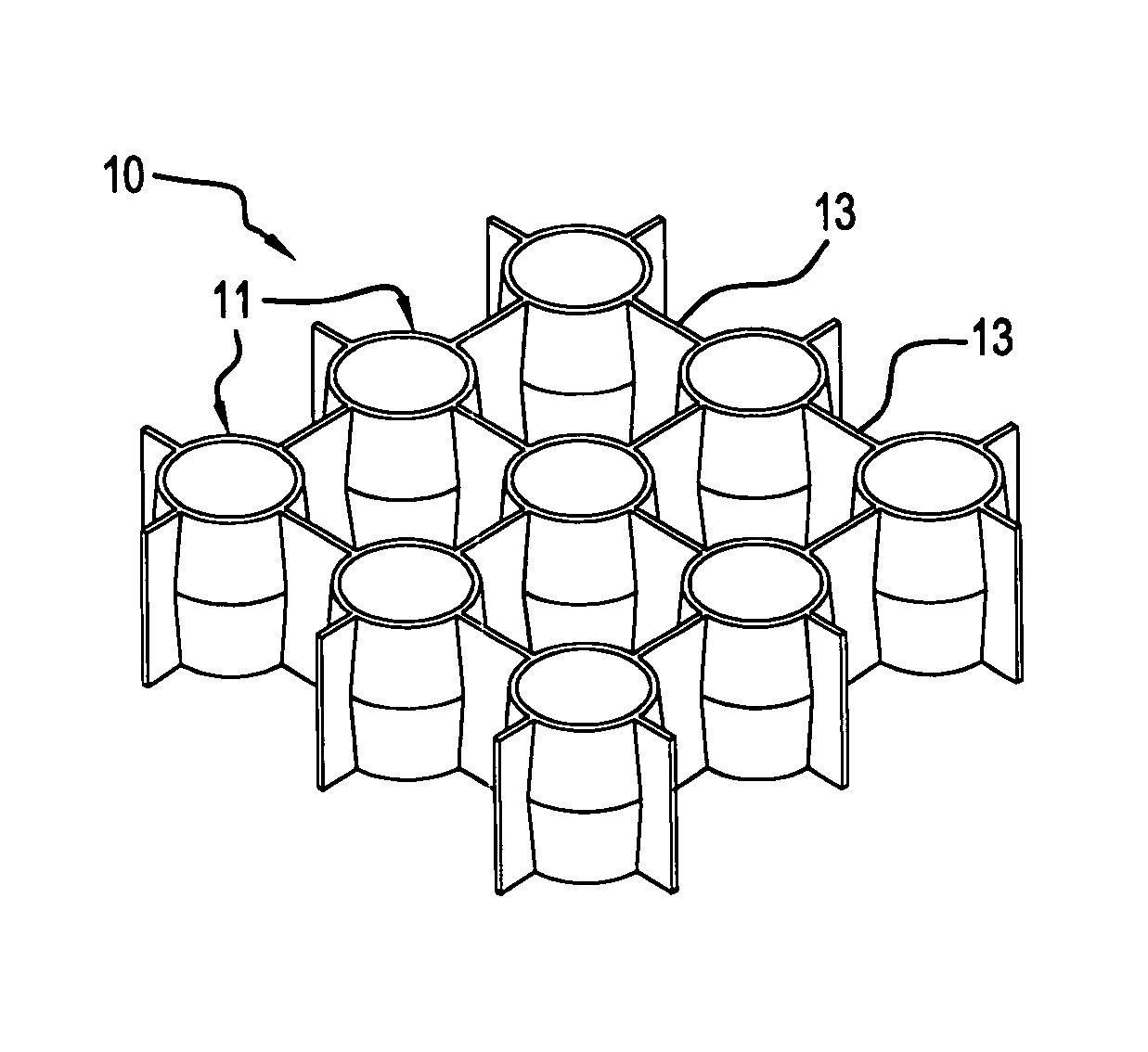
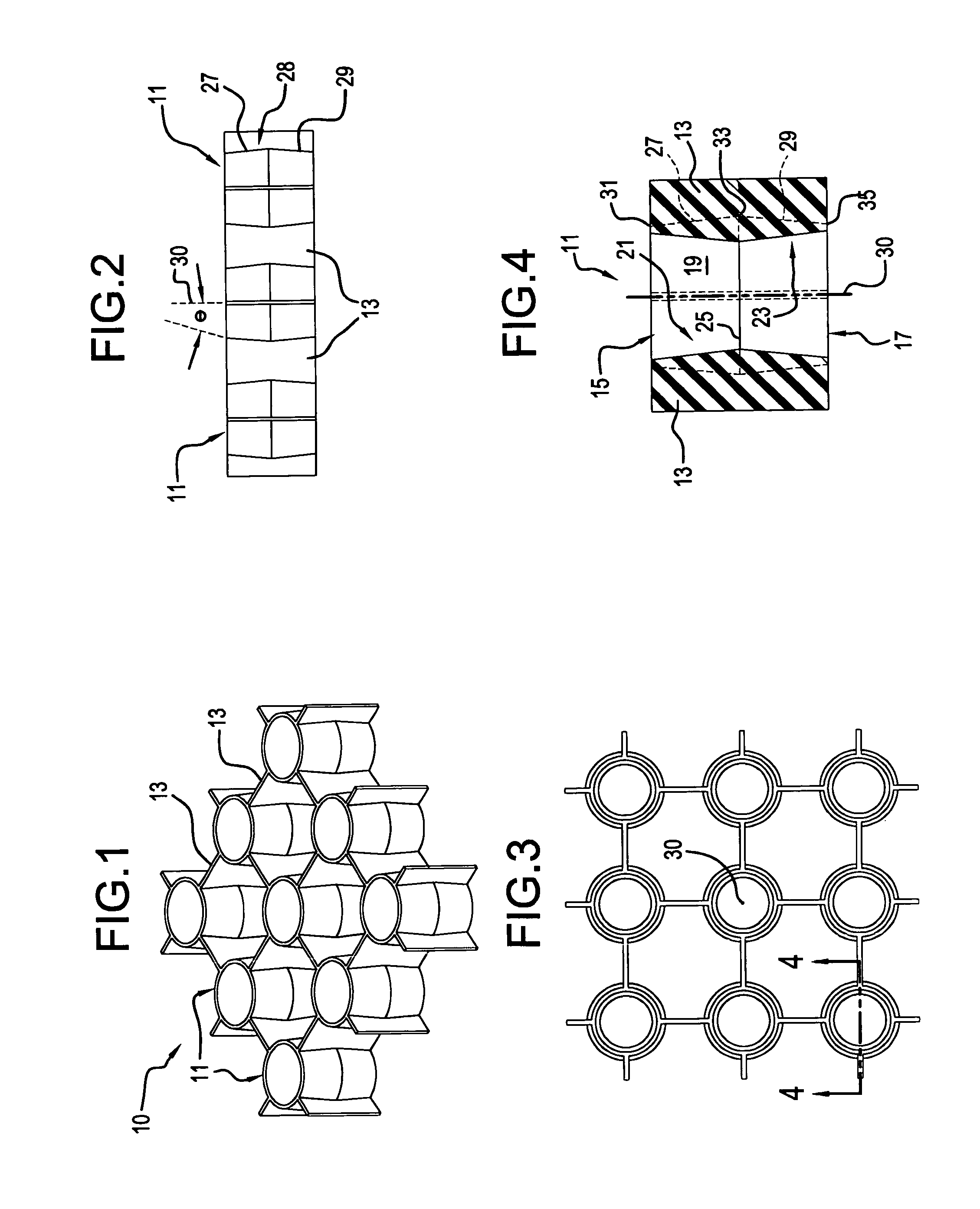
[0030]With reference first to FIG. 1, a preferred embodiment of the present invention is generally designated by the reference numeral 10, and is seen to include a plurality of tubular members 11 interconnected with webs or webbing 13 comprising means for maintaining the axes of elongation 30 of the members 11 substantially parallel. In the example shown, the tubular members are arranged in a square matrix with even spacing between one tubular member and tubular members to the sides thereof. Thus, in the example shown, one tubular member is surrounded by four adjacent tubular members at 90 degree spacing about the circumference of the centrally located tubular member 11, with each of these members being interconnected through the webbing 13. This is also shown with particular reference to FIGS. 2 and 3. Of course, any means may be employed to maintain tubular members in spaced parallel relation.

[0031]With reference to FIGS. 2 and 4, the specific details of each tubular member 11 bec...


PUM

PropertyMeasurementUnit
thicknessaaaaaaaaaa
thicknessaaaaaaaaaa
angleaaaaaaaaaa

Abstract

A lateral displacement shock absorbing material includes a material consisting of elongated tubular impact absorbing members, each having an axis of elongation. The axes of elongation are parallel to one another by virtue of lateral webbing interconnecting them together. Each of the tubular members has an outer surface made up of two frustoconical surfaces with their larger diameter ends abutting one another and their smaller diameter ends facing away from one another. Each tubular member includes a passageway defined by two frustoconical shapes with the smaller diameter ends abutting one another, and the larger diameter ends facing away from one another and defining the openings of each passageway. Upon impact, the side walls of the tubular members bulge or displace laterally to absorb impacts.

Description

BACKGROUND OF THE INVENTION[0001]The present invention relates to lateral displacement shock absorbing material. The present invention relates to a new way to attenuate impacts using tubular structures having non-uniform wall cross-sections placed at an angle to the direction of impact.[0002]The objective achieved through operation of an impact attenuating material is absorption and dissipation of energy. This is accomplished when one object impacts another by slowing down the movement of the first object in a controlled manner. During the process of energy absorption, the impact attenuating material is compressed.[0003]The degree of impact absorption achievable by an impact attenuating material is directly related to the difference between the pre-impact thickness and the thickness of the material when compressed to the maximum degree. Impact absorbing materials known in the prior art such as expanded polystyrene, expanded polypropylene, air bladders, and others bottom out when the...

Claims


Application Information

Patent Timeline
Patent Type & Authority Patents(United States)
IPC IPC(8): F16F3/08
CPCA42B3/064A42B3/124F16F7/121F16F1/44
Inventor DARNELL, ERICBRINE, III, WILLIAM
Owner CASCADE MAVERIK LACROSSE LLC
Why Eureka
Try Eureka