
Liquid ejection apparatus and liquid agitation method

a technology of liquid ejection and agitation method, which is applied in the direction of printing, etc., can solve the problems of poor color reproduction, non-uniform density or distortion, deterioration of quality, etc., and achieve the effect of preventing deterioration of liquid due to aggregation and/or sedimentation of micro-particles in the liquid, efficiently and satisfactorily agitating the liquid for ejection, and large displacement of liquid

Inactive Publication Date: 2010-03-16
FUJIFILM CORP
View PDF16 Cites 42 Cited by
  • Summary
  • Abstract
  • Description
  • Claims
  • Application Information

AI Technical Summary

Benefits of technology

[0017]The present invention has been contrived in view of the foregoing circumstances, an object thereof being to provide a liquid ejection apparatus and a liquid agitation method whereby the liquid to be ejected can be agitated efficiently and satisfactorily.
[0018]More specifically, firstly, the object is to provide a liquid ejection apparatus and a liquid agitation method, whereby deterioration of liquid quality due to aggregation and sedimentation of the micro-particles in the liquid in the vicinity of the ejection port can be prevented, and liquid can be ejected stably. Secondly, the object is to provide a liquid ejection apparatus and a liquid agitation method whereby the liquid inside the apparatus can be set to a uniform density and can be agitated efficiently. Thirdly, the object is to provide a liquid ejection apparatus and a liquid agitation method whereby the liquid inside the liquid ejection head can be agitated satisfactorily.

Problems solved by technology

When the liquid in which the micro-particles have aggregated and settled is ejected, then there is deterioration of quality in the ejection results, namely, density non-uniformities or distortions, poor color reproduction, non-uniform density of the micro-particles, and the like.
In particular, in a liquid ejection apparatus having a liquid ejection head in which the liquid ejection face is situated in a bottommost position, nozzle blockages are liable to occur due to sedimented micro-particles in the nozzles.
Methods for agitating the liquid have been proposed, but it is difficult to agitate the liquid with good efficiency.
In Japanese Patent Application Publication Nos. 6-87220 and 2002-96484, the voltage of the input signal (drive signal) applied to the piezoelectric elements must be set within a range that does not cause liquid ejection, it is then impossible to vibrate the liquid with a relatively large amplitude, and hence a sufficient agitation effect cannot be obtained.
More specifically, under the drive conditions in the range that does not cause the liquid ejection, the agitation performance inside the pressure chamber is poor and improvement in the state of micro-particles that have aggregated and sedimented in the vicinity of the nozzle openings cannot be expected.
For example, in Japanese Patent Application Publication No. 2003-72104, the liquid agitation devices are required in the manifold, the supply channels and the container; hence, not only does this raise costs, but it also leads to increase in the size of the apparatus.
However, in practice, it is difficult to provide liquid agitation devices in all of the locations in which the liquid is present separately within the apparatus.
Furthermore, in general, when the apparatus is left in a power-off state, the liquid ejection operation and the liquid supply operation are halted and no liquid agitation operation is carried out for a long period of time.
Hence, there is a problem in that the preparation duration before carrying out liquid ejection becomes long.

Method used


Image

  • Liquid ejection apparatus and liquid agitation method
  • Liquid ejection apparatus and liquid agitation method
  • Liquid ejection apparatus and liquid agitation method

Examples


Embodiment Construction

Liquid Ejection Head

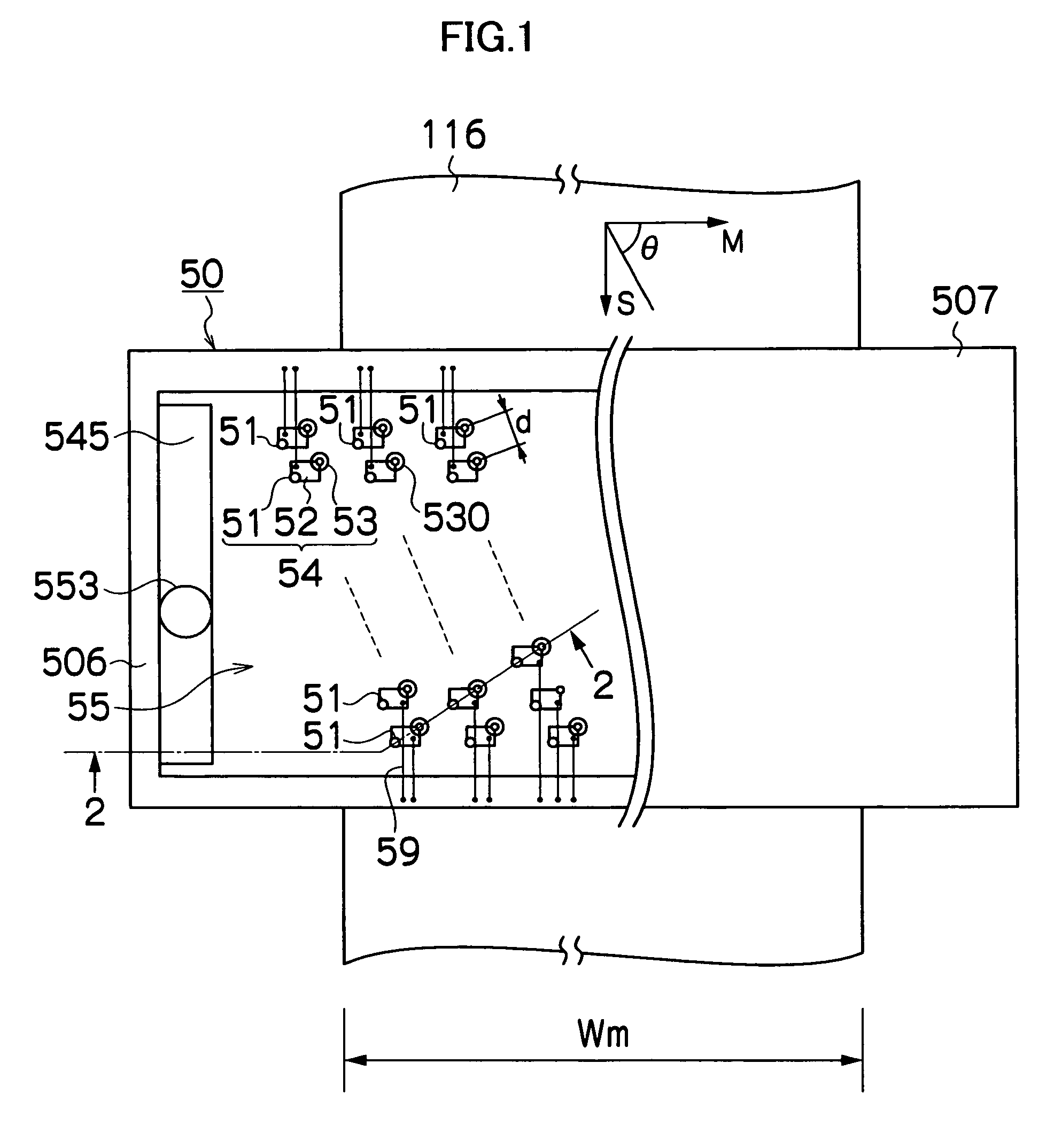
[0078]FIG. 1 is a plan diagram showing the general structure of a liquid ejection head in a liquid ejection device according to an embodiment of the present invention, giving a perspective view of the left-hand half in the diagram.

[0079]The liquid ejection head 50 shown in FIG. 1 is a so-called full line head, having a structure in which a plurality of liquid ejection ports or nozzles 51, which eject liquid toward an ejection receiving medium or a recording medium 116, are arranged through a length corresponding to a width Wm of the recording medium 116 in a main scanning direction indicated by arrow M in FIG. 1 perpendicular to a sub-scanning direction indicated by arrow S in FIG. 1, which is a conveyance direction of the recording medium 116.

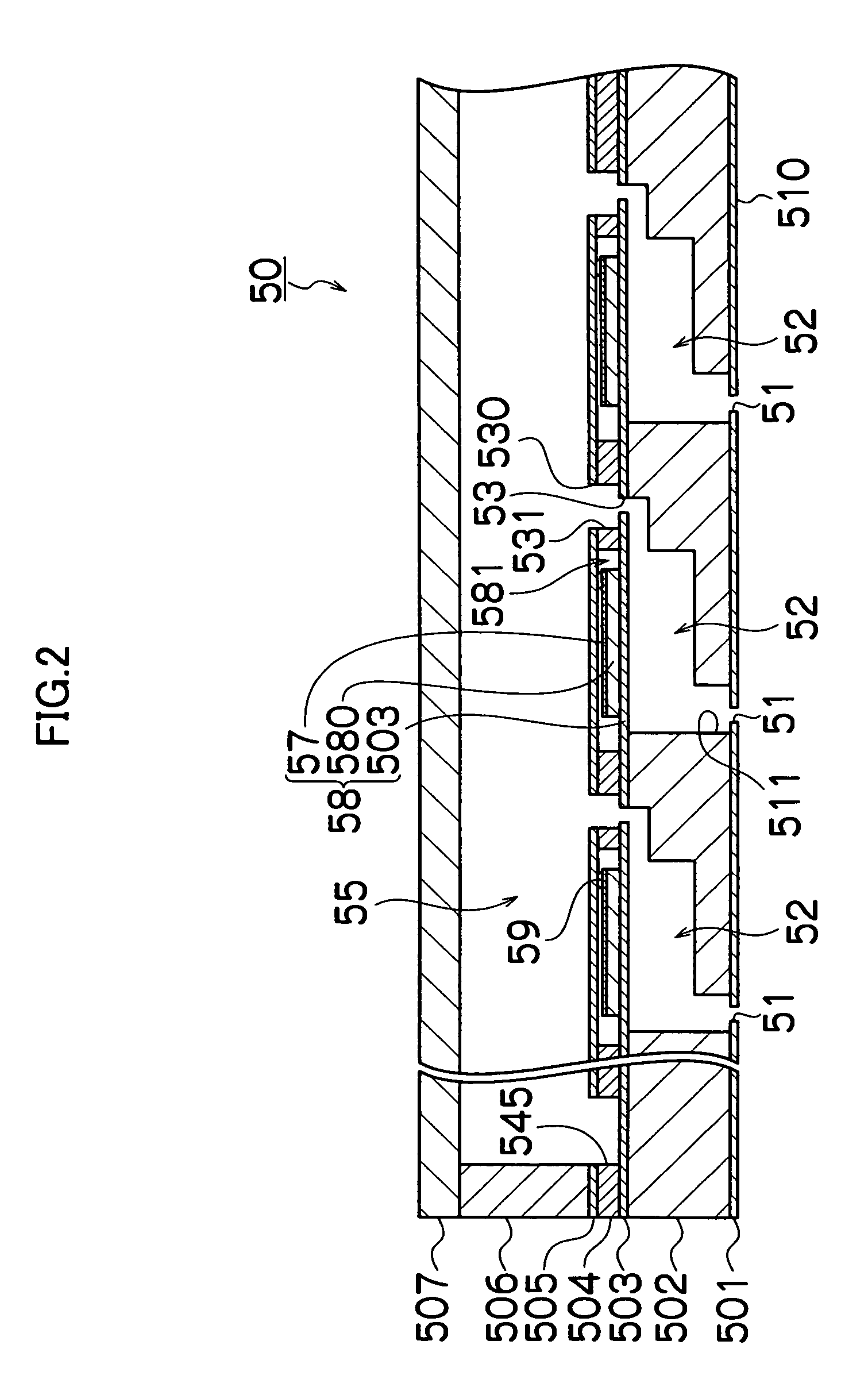
[0080]More specifically, the liquid ejection head 50 has a composition in which a plurality of pressure chamber units 54, each having the nozzle 51, a pressure chamber 52 connected to the nozzle 51, and an opening section s...


PUM


Abstract

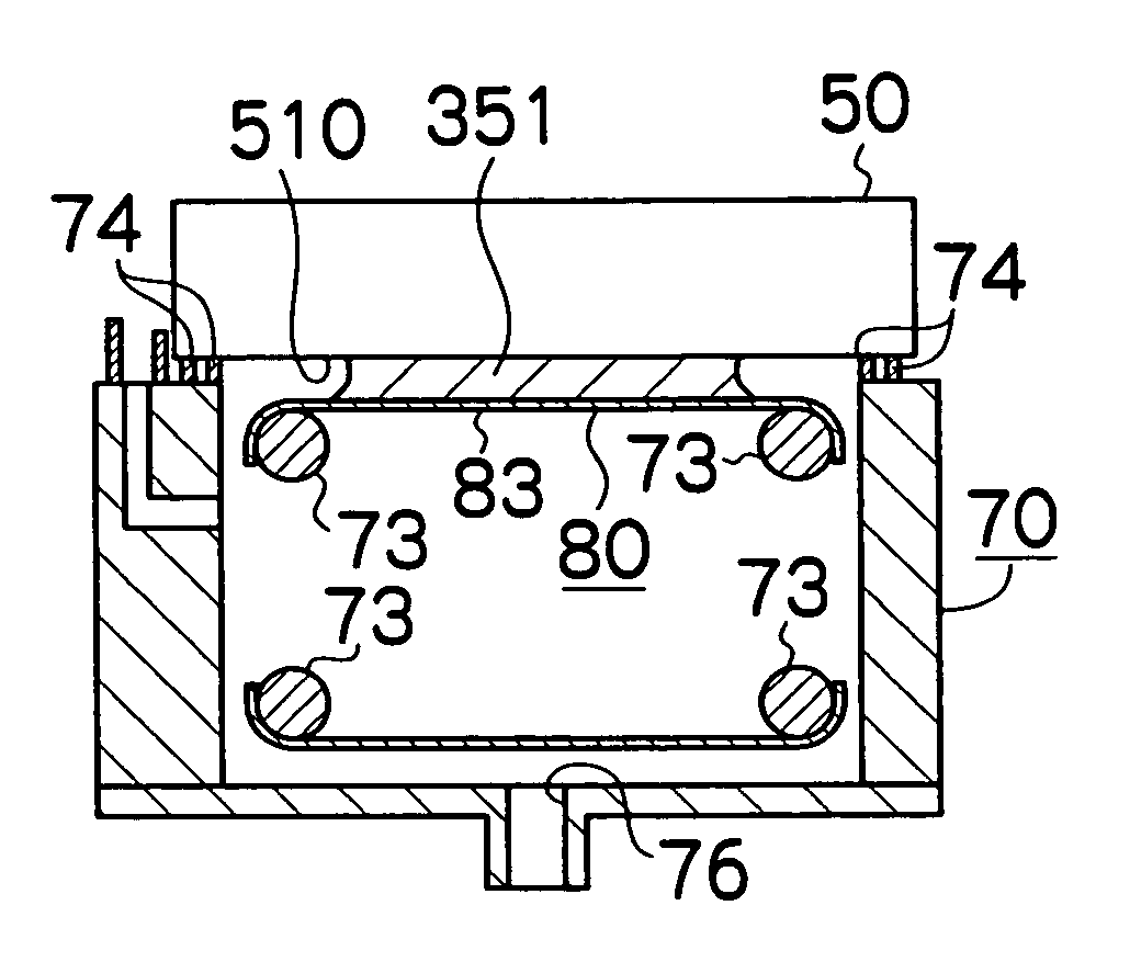
A liquid ejection apparatus which ejects liquid toward a prescribed medium is provided. The apparatus includes a liquid ejection head which has an ejection port ejecting liquid, and an energy application element applying energy to the liquid to be ejected from the ejection port; and a liquid receiving device which is opposite to the ejection port and receives the liquid ejected from the ejection port. The liquid received by the liquid receiving device forms a liquid pool between the liquid receiving device and the ejection port and the liquid is agitated by a driving device which applies a drive signal to the energy application element.

Description

BACKGROUND OF THE INVENTION[0001]1. Field of the Invention[0002]The present invention relates to a liquid ejection apparatus and a liquid agitation method, and more particularly, to a liquid ejection apparatus which ejects liquid toward a prescribed medium and a liquid agitation method for agitating the liquid.[0003]2. Description of the Related Art[0004]There is a liquid ejection apparatus which ejects dispersion liquid in which dispersed micro-particles are suspended. Examples of material of the micro-particles include, for instance, pigment, high-polymer resin, metal, glass, or oxide or compound of these. Generally, the micro-particles tend to aggregate and settle with the passage of time. When the liquid in which the micro-particles have aggregated and settled is ejected, then there is deterioration of quality in the ejection results, namely, density non-uniformities or distortions, poor color reproduction, non-uniform density of the micro-particles, and the like. Therefore, tec...

Claims


Application Information

Patent Timeline
Patent Type & Authority Patents(United States)
IPC IPC(8): B41J2/165
CPCB41J2/16585B41J2/1707B41J2/175
Inventor TAKATSUKA, TSUTOMU
Owner FUJIFILM CORP
Learn More