Liquid ejection apparatus and liquid agitation method

a technology of liquid ejection and agitation method, which is applied in the direction of printing, etc., can solve the problems of poor color reproduction, non-uniform density or distortion, deterioration of quality, etc., and achieve the effect of preventing deterioration of liquid due to aggregation and/or sedimentation of micro-particles in the liquid, efficiently and satisfactorily agitating the liquid for ejection, and large displacement of liquid

Inactive Publication Date: 2007-05-24
FUJIFILM CORP
View PDF10 Cites 18 Cited by
  • Summary
  • Abstract
  • Description
  • Claims
  • Application Information

AI Technical Summary

Benefits of technology

[0054] According to the present invention, it is possible to agitate the liquid for ejection efficiently and satisfactorily. Moreover, the liquid in the apparatus can be maintained at a uniform density. Furthermore, it is possible to satisfactorily agitate the liquid

Problems solved by technology

When the liquid in which the micro-particles have aggregated and settled is ejected, then there is deterioration of quality in the ejection results, namely, density non-uniformities or distortions, poor color reproduction, non-uniform density of the micro-particles, and the like.
In particular, in a liquid ejection apparatus having a liquid ejection head in which the liquid ejection face is situated in a bottommost position, nozzle blockages are liable to occur due to sedimented micro-particles in the nozzles.
Methods for agitating the liquid have been proposed, but it is difficult to agitate the liquid with good efficiency.
In Japanese Patent Application Publication Nos. 6-87220 and 2002-96484, the voltage of the input signal (drive signal) applied to the piezoelectric elements must be set within a range that does not cause liquid ejection, it is then impossible to vibrate the liquid with a relatively large amplitude, and hence a sufficient agitation effect cannot be obtained.
More specifically, under the drive co

Method used


Image

  • Liquid ejection apparatus and liquid agitation method
  • Liquid ejection apparatus and liquid agitation method
  • Liquid ejection apparatus and liquid agitation method

Examples


Embodiment Construction

Liquid Ejection Head

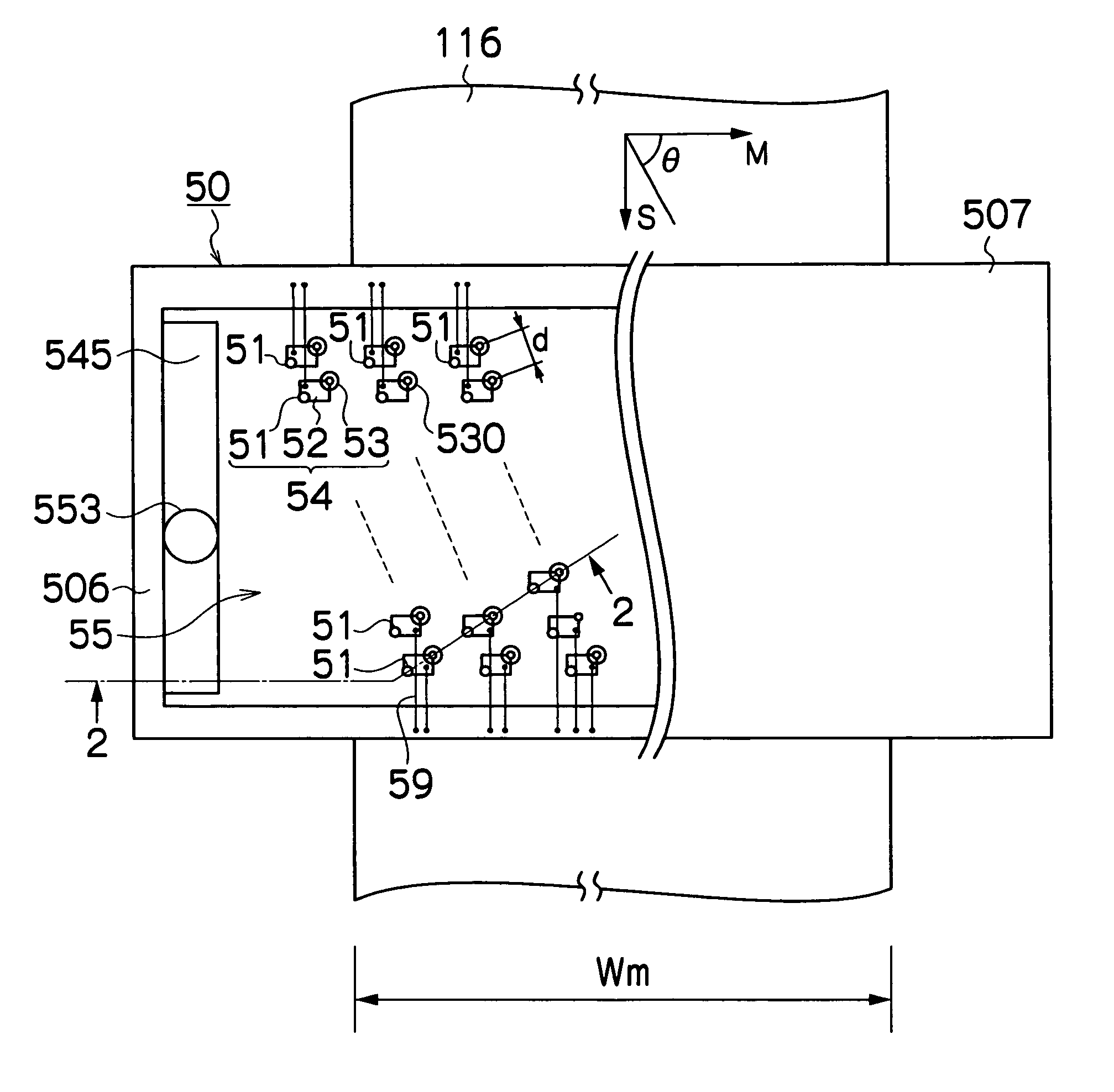
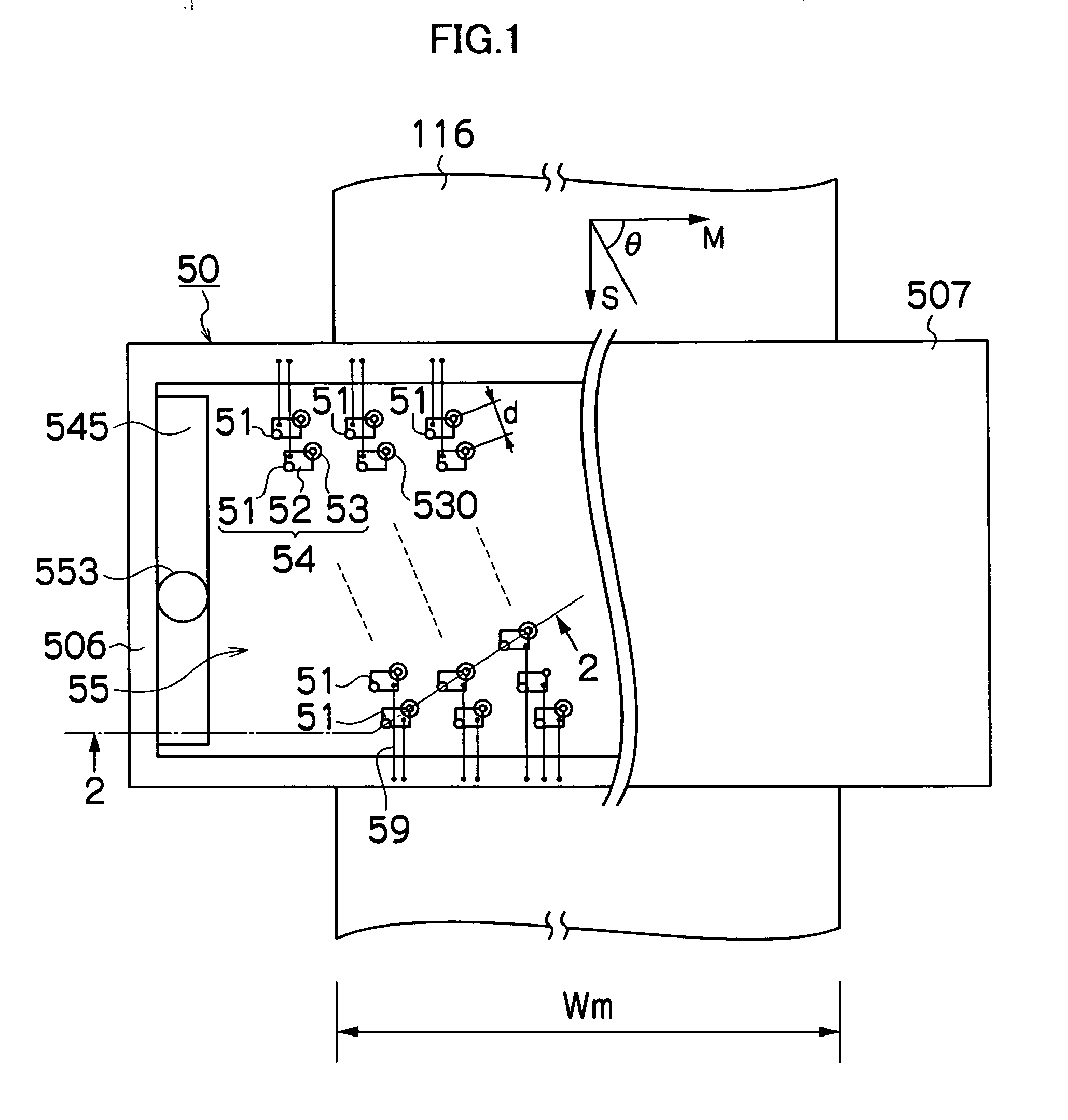
[0078]FIG. 1 is a plan diagram showing the general structure of a liquid ejection head in a liquid ejection device according to an embodiment of the present invention, giving a perspective view of the left-hand half in the diagram.

[0079] The liquid ejection head 50 shown in FIG. 1 is a so-called full line head, having a structure in which a plurality of liquid ejection ports or nozzles 51, which eject liquid toward an ejection receiving medium or a recording medium 116, are arranged through a length corresponding to a width Wm of the recording medium 116 in a main scanning direction indicated by arrow M in FIG. 1 perpendicular to a sub-scanning direction indicated by arrow S in FIG. 1, which is a conveyance direction of the recording medium 116.

[0080] More specifically, the liquid ejection head 50 has a composition in which a plurality of pressure chamber units 54, each having the nozzle 51, a pressure chamber 52 connected to the nozzle 51, and an opening sec...


PUM


Abstract

The liquid ejection apparatus includes: a liquid ejection head which has an ejection port ejecting liquid, and an energy application element applying energy to the liquid to be ejected from the ejection port; a liquid receiving device which is opposite to the ejection port and receives the liquid ejected from the ejection port, the liquid received by the liquid receiving device forming a liquid pool between the liquid receiving device and the ejection port; and a driving device which applies a drive signal to the energy application element in a state where the liquid pool has been formed, so as to agitate the liquid at least in a vicinity of the ejection port.

Description

BACKGROUND OF THE INVENTION [0001] 1. Field of the Invention [0002] The present invention relates to a liquid ejection apparatus and a liquid agitation method, and more particularly, to a liquid ejection apparatus which ejects liquid toward a prescribed medium and a liquid agitation method for agitating the liquid. [0003] 2. Description of the Related Art [0004] There is a liquid ejection apparatus which ejects dispersion liquid in which dispersed micro-particles are suspended. Examples of material of the micro-particles include, for instance, pigment, high-polymer resin, metal, glass, or oxide or compound of these. Generally, the micro-particles tend to aggregate and settle with the passage of time. When the liquid in which the micro-particles have aggregated and settled is ejected, then there is deterioration of quality in the ejection results, namely, density non-uniformities or distortions, poor color reproduction, non-uniform density of the micro-particles, and the like. Theref...

Claims


Application Information

Patent Timeline
IPC IPC(8): B41J2/05
CPCB41J2/16585B41J2/1707B41J2/175
Inventor TAKATSUKA, TSUTOMU
Owner FUJIFILM CORP
Why Eureka
Try Eureka