
Liquid ejection apparatus, image forming apparatus, and liquid ejection method

a technology of liquid ejection and image forming, which is applied in the direction of printing, other printing apparatus, etc., can solve problems such as failure of ejection, and achieve the effect of preventing aggregation or sedimentation of coloring materials

Inactive Publication Date: 2008-07-17
FUJIFILM CORP
View PDF2 Cites 2 Cited by
  • Summary
  • Abstract
  • Description
  • Claims
  • Application Information

AI Technical Summary

Benefits of technology

[0009]The present invention has been contrived in view of the foregoing circumstances, an object thereof being to provide a liquid ejection apparatus, an image forming apparatus and a liquid ejection method, whereby an ejection liquid can be ejected stably by securing gas barrier properties and preventing aggregation or sedimentation of the coloring material, or the like, contained in the ejection liquid.

Problems solved by technology

If the aggregate or sediment caused by the aggregation or sedimentation of the coloring material, or the like, flows into the recording head during ejection of the ink, then ejection failure will arise.

Method used


Image

  • Liquid ejection apparatus, image forming apparatus, and liquid ejection method
  • Liquid ejection apparatus, image forming apparatus, and liquid ejection method
  • Liquid ejection apparatus, image forming apparatus, and liquid ejection method

Examples


Embodiment Construction

Description of Liquid Ejection Apparatus and Method

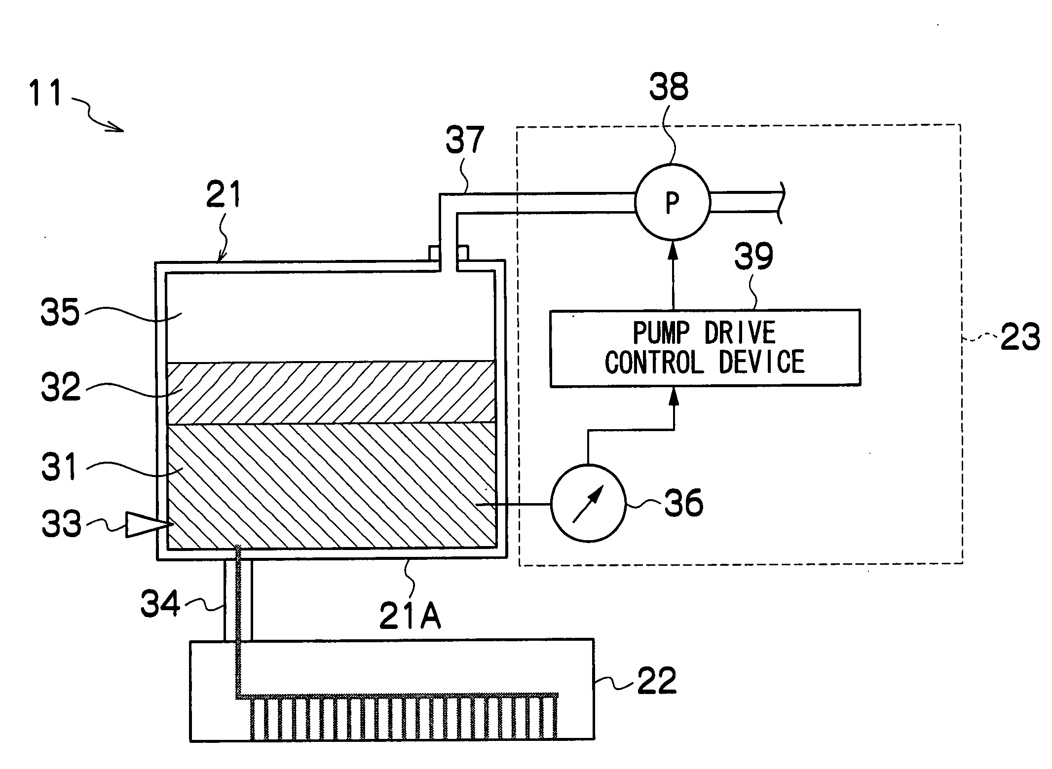
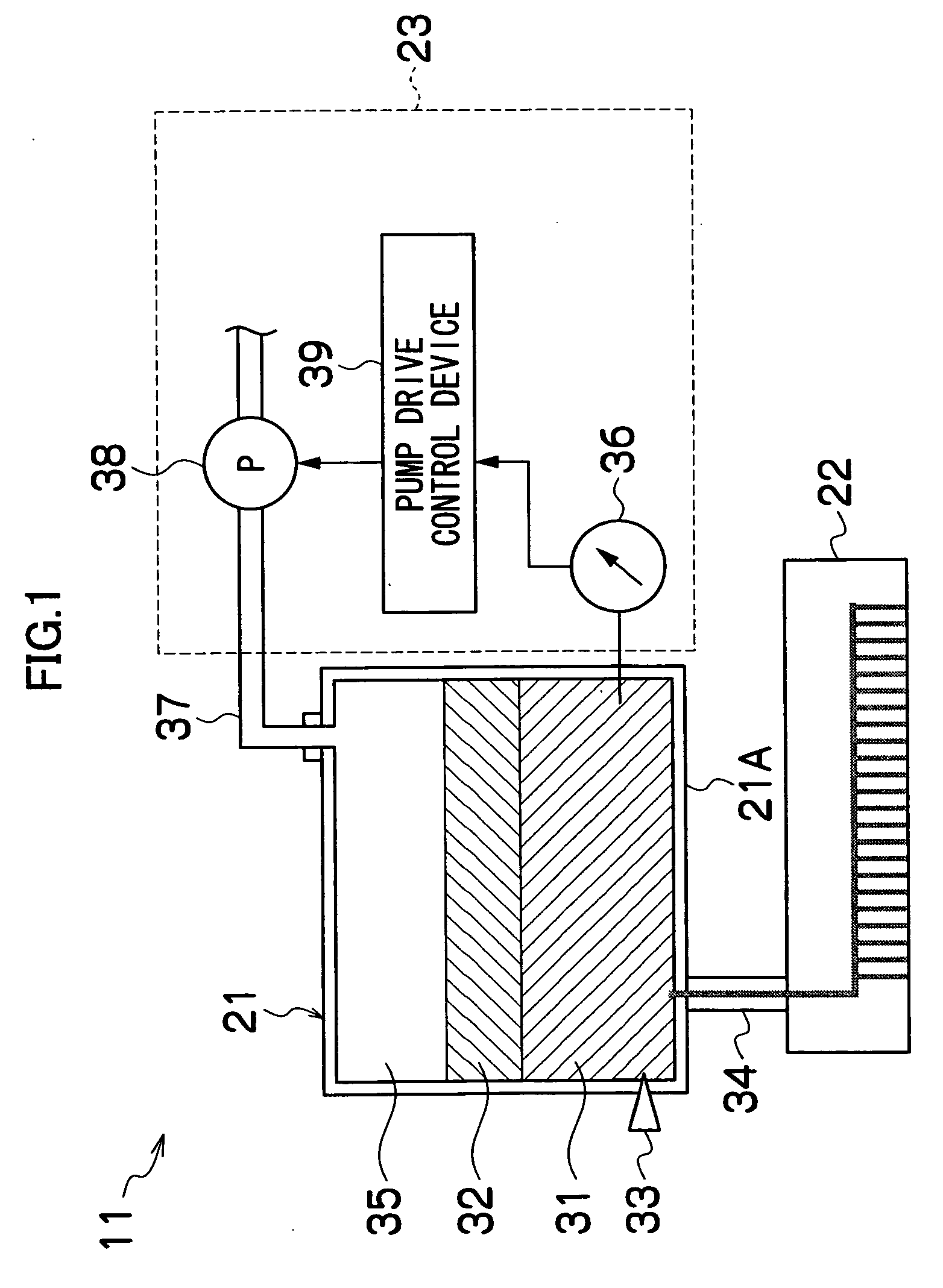
[0050]FIG. 1 is a general schematic drawing of a liquid ejection apparatus according to an embodiment of the present invention. As shown in FIG. 1, a liquid ejection apparatus 11 according to the present embodiment is principally constituted by a liquid accommodation unit 21, a recording head 22, a pressure adjustment device 23, and the like. The liquid accommodation unit 21 has an enclosure 21A in which an ejection liquid (i.e., liquid to be ejected from the recording head 22) 31, a non-volatile liquid 32 and air 35 are accommodated, and a liquid detection device 33 is also provided in the enclosure 21A. The liquid accommodation unit 21 is connected to the recording head 22 by means of a connection channel 34. The pressure adjustment device 23 is constituted by a pressure measurement device 36 which measures the pressure of the ejection liquid 31 in the enclosure 21A of the liquid accommodation unit 21, a pump 38 disposed in a flow...


PUM


Abstract

The liquid ejection apparatus includes: a recording head which includes a nozzle and an ejection device, the ejection device ejecting an ejection liquid through the nozzle by applying pressure to the ejection liquid in the recording head; a liquid accommodation unit which is in connection with the recording head and which accommodates a gas, the ejection liquid to be supplied to the recording head, and a non-volatile liquid having a permeability to the gas lower than the ejection liquid, the ejection liquid being separated from the gas by the non-volatile liquid; and a pressure control unit which controls pressure of the ejection liquid in the liquid accommodation unit by moving the gas into and out of the liquid accommodation unit.

Description

BACKGROUND OF THE INVENTION[0001]1. Field of the Invention[0002]The present invention relates to a liquid ejection apparatus, an image forming apparatus and a liquid ejection method, and more particularly, to a liquid ejection apparatus and a liquid ejection method whereby an ejection liquid can be ejected stably by securing gas barrier properties and preventing aggregation or sedimentation of the coloring material, or the like, contained in the ejection liquid.[0003]2. Description of the Related Art[0004]Japanese Patent Application Publication No. 2005-041048 discloses a liquid spraying apparatus which is mainly constituted of a recording head 222, an ink cartridge 221, a pressure control unit 223, as shown in FIG. 15. The ink cartridge 221 is connected with a pump 238 in the pressure control unit 223 via a pressure control valve 229 by means of a pressure control tube 237. The pressure sensor 236, which is connected with the ink cartridge 221 via the pressure control tube 237, mea...

Claims


Application Information

Patent Timeline
Patent Type & Authority Applications(United States)
IPC IPC(8): B41J2/015
CPCB41J2/17509B41J29/38B41J2/17596B41J2/17556
Inventor KOJIMA, TOSHIYAFURUKAWA, GENTARO
Owner FUJIFILM CORP
Learn More