Device for adjusting the centring of a turbo-engine pivoting vane control synchronization ring

a technology of pivoting vane and control ring, which is applied in the direction of machines/engines, reaction engines, liquid fuel engines, etc., can solve the problems of vibration of the control ring, loss of pad adjustment, and device for adjusting the pads in the control ring cannot provide perfect immobilization of the pad adjustment threaded rod, etc., to achieve simple design and eliminate the effect of drawbacks

Active Publication Date: 2010-03-16
SN DETUDE & DE CONSTR DE MOTEURS DAVIATION S N E C M A
View PDF8 Cites 9 Cited by
  • Summary
  • Abstract
  • Description
  • Claims
  • Application Information

AI Technical Summary

Benefits of technology

[0008]The principal object of this invention is to mitigate these drawbacks by proposing a device for adjusting control ring concentricity which is simple in design and reliable during all the phases of turbo-engine operation.
[0010]The pads are adjusted in the radial direction by screwing the threaded rod more or less into the control ring. Once the correct adjustment has been carried out, the pad holder rod is locked in position by pinching the slot in a longitudinal direction. Therefore, this adjusting device comprises few parts, which makes it simple in design and is capable of providing reliable locking of the pads, irrespective of the phase of turbo-engine operation.

Problems solved by technology

These devices for adjusting the pads in the control ring are not capable of providing perfect immobilization of the pad adjustment threaded rod during all the operating phases of the turbo-engine.
In fact, when some pads are no longer in contact with the casing shell, wear of the adjustment rod threads is caused by vibration, which leads to loss of adjustment of the pads and consequently vibration of the control ring, this vibration being particularly detrimental in terms of vane pitch precision.

Method used


Image

  • Device for adjusting the centring of a turbo-engine pivoting vane control synchronization ring
  • Device for adjusting the centring of a turbo-engine pivoting vane control synchronization ring
  • Device for adjusting the centring of a turbo-engine pivoting vane control synchronization ring

Examples


Embodiment Construction

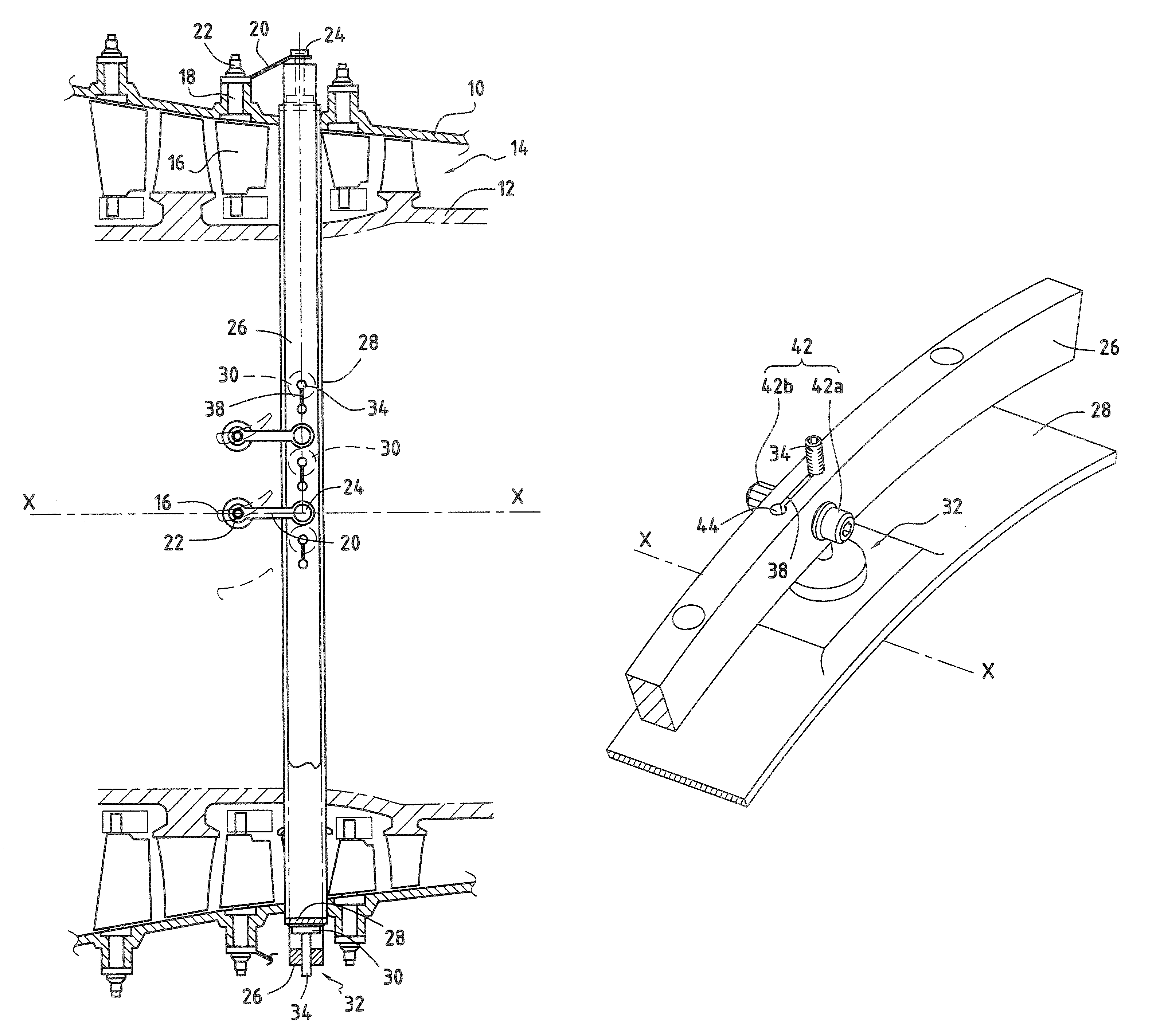
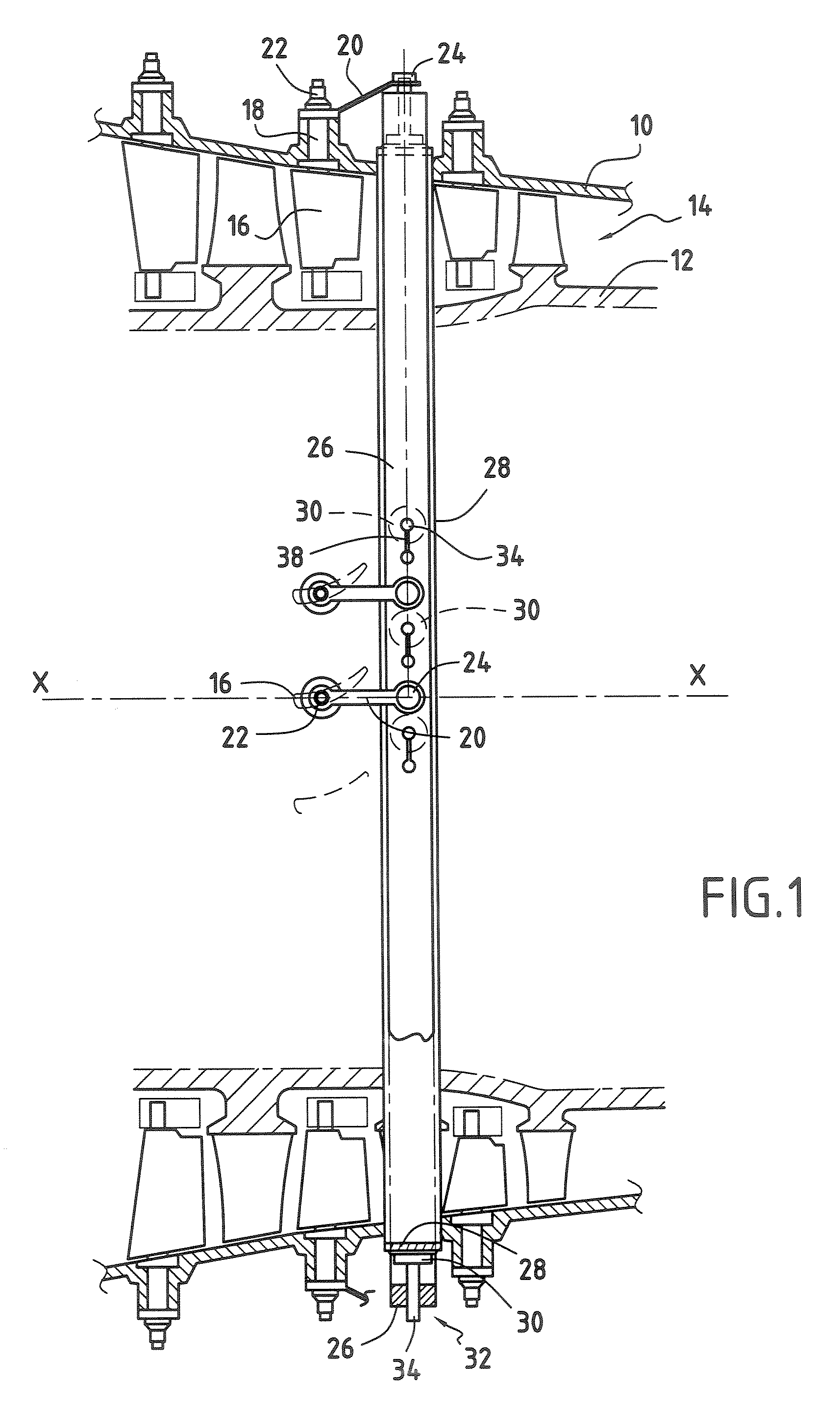
[0019]FIG. 1 partially shows a turbo-engine compressor. The compressor comprises a stator shell 10 which is centred on longitudinal axis X-X of the turbo-engine and which surrounds a rotor 12 in such a way as to define with the latter an annular stream 14 for flow of the gases.

[0020]The compressor also comprises a plurality of vanes which form several stages in the stream 14. Some of these stages are formed by variable pitch vanes 16. These vanes 16 pivot about a radial pin 18 which goes through the stator shell 10.

[0021]Each pin (or pivot) 18 of the variable pitch vanes 16 is connected to one end of a connecting rod or control lever 20 via a connector 22. The other end of the connecting rods 20 is articulated about pins 24 arranged radially on a control ring 26. The latter surrounds a cylindrical shell 28 of the casing of the turbo-engine, which is centred on the longitudinal axis X-X of the latter. The control ring 26 and the cylindrical shell 28 are arranged concentrically with e...


PUM


Abstract

The invention relates to a device for adjusting the centring of a turbo-engine pivoting vane control ring, comprising a control ring (26) centred on a longitudinal axis (X-X) of the turbo-engine and provided with a plurality of tapped holes (36) running in a radial direction and a plurality of pad holders (32), each comprising a threaded rod (34) screwed into one of the ring's tapped holes (36), each pad holder (32) holding, at an inner end, a pad (30) intended to come into contact with a cylindrical shell (28), coaxial with the ring. The control ring (26) comprises, in addition, a plurality of slots (38) running in a tangential direction, each slot (38) communicating with one of the ring's tapped holes (36) The device comprises means (40, 42a, 42b) of pinching, in a longitudinal direction, each of the slots (38) in such a way as to lock the pad holders (32) in position.

Description

BACKGROUND OF THE INVENTION[0001]This invention relates to the general area of devices for adjusting the centring of a ring for synchronization of control of pivoting vanes of a turbo-engine on the latter's axis.[0002]In a turbo-engine, it is a known practice to use one or several stages of stator vanes for adjusting the flow and direction of flow of the gases going through the compression section in accordance with the operating conditions of the turbo-engine. These stages of stator vanes comprise a plurality of vanes (called variable pitch vanes) which may pivot about their pins connecting them to the stator in such a way as to alter their pitch angle in accordance with the operating conditions of the turbo-engine.[0003]The known devices for controlling variable pitch vanes usually comprise a ring surrounding a cylindrical shell of the turbo-engine casing and a plurality of levers or connecting rods, each connecting rod having a first end coupled to the control ring by a joint and...

Claims


Application Information

Patent Timeline
Patent Type & Authority Patents(United States)
IPC IPC(8): F01D17/12
CPCF01D17/162F04D29/563F05D2250/411
Inventor BROMANN, ALAIN MARC LUCIEN
Owner SN DETUDE & DE CONSTR DE MOTEURS DAVIATION S N E C M A
Why Eureka
Try Eureka