
Printed board connector with ground connection

a technology of printed board and ground connection, which is applied in the direction of connection contact member material, coupling device connection, coupling protective earth/shielding arrangement, etc., can solve the problems that the known connector of this type naturally is correspondingly complex in construction and manufacture, and achieves high mating cycle, increased wear, and high friction

Active Publication Date: 2010-03-16
HARTING ELECTRIC GMBH & CO KG
View PDF12 Cites 2 Cited by
  • Summary
  • Abstract
  • Description
  • Claims
  • Application Information

AI Technical Summary

Benefits of technology

"The invention is a device that ensures safe discharge of static electric energy before a printed board is connected to a voltage supply. This is achieved by arranging an electrically conductive grounding contact in the connector and providing a grounding strip on the printed board that slides along the grounding contact during insertion. The printed board connector is designed to prevent uncontrolled discharges of static electric energy and ensure a potential equalization between the grounded lines of the printed board and the system during the mating process. The grounding contact is integrated into the connector housing and connected to the printed board through a spring-type contacting or a press-in pin. The printed board can also have a grounded strip conductor on its edge to optimize ground contact. The printed board connector withstands high mating cycles due to increased wear caused by friction between the plastic wall and the printed board edges."

Problems solved by technology

Known connectors of this type naturally are correspondingly complex with respect to their construction and manufacture.

Method used


Image

  • Printed board connector with ground connection
  • Printed board connector with ground connection
  • Printed board connector with ground connection

Examples


Embodiment Construction

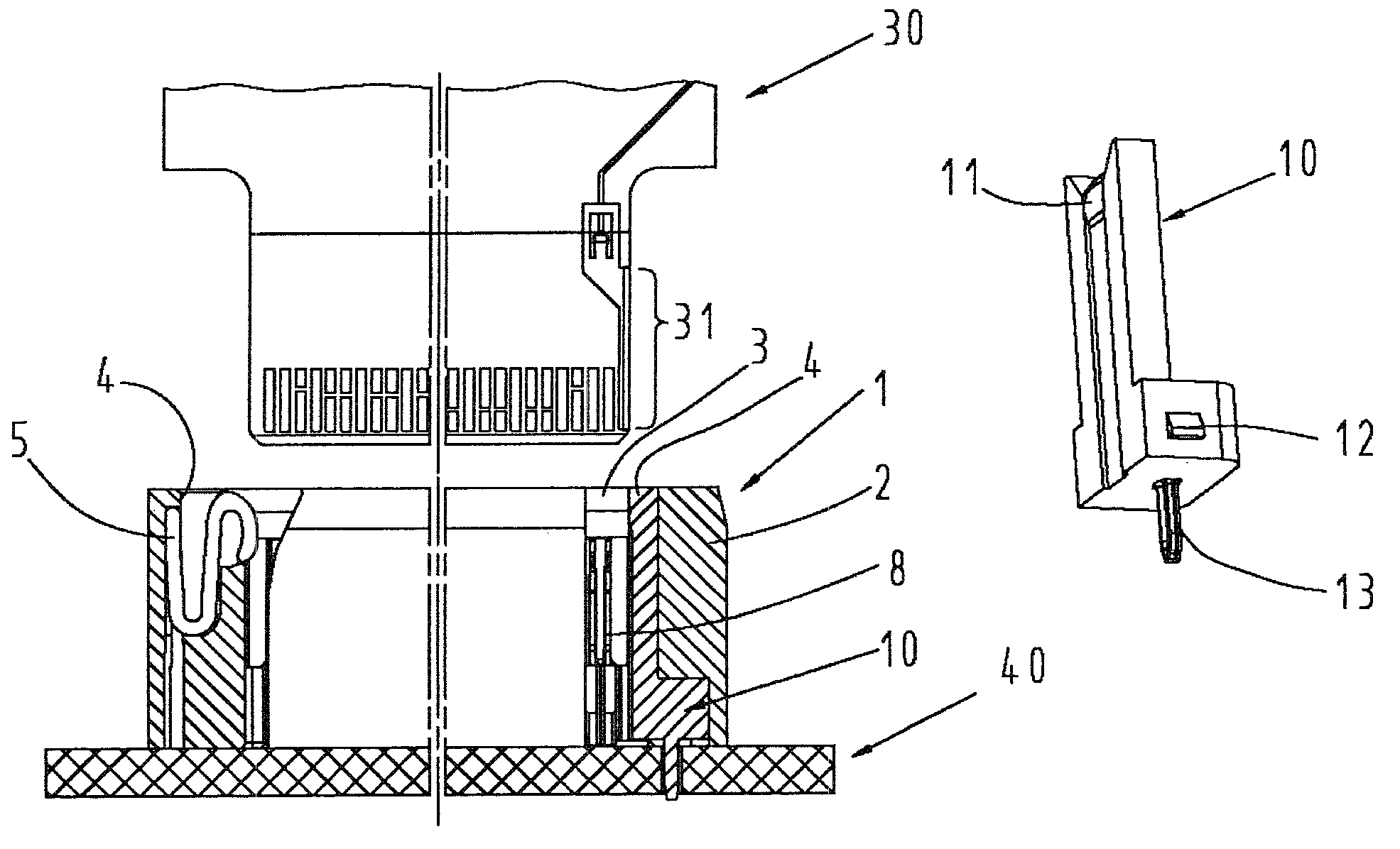
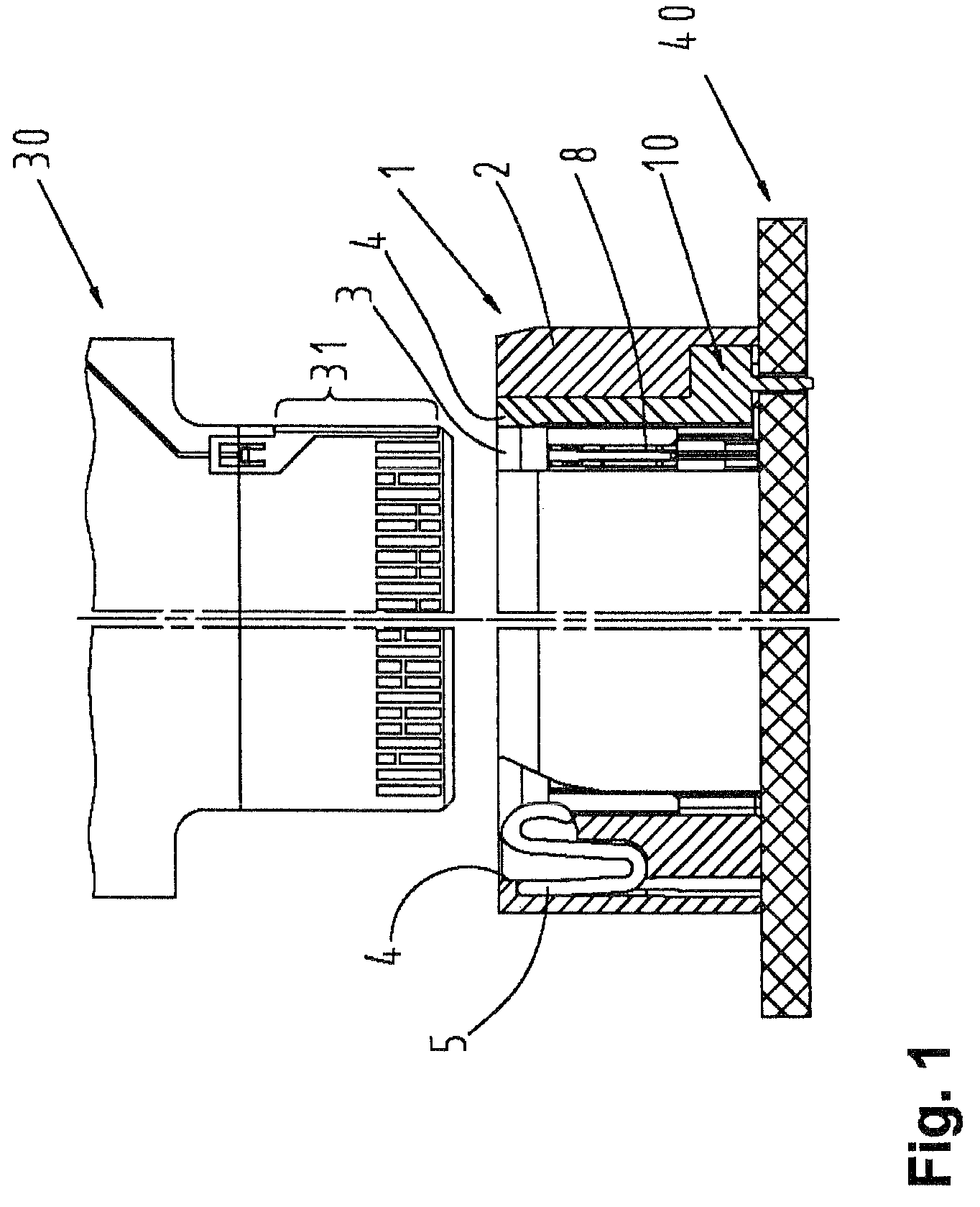
[0032]FIG. 1 shows a partial section through a printed board connector 1 that is mounted on a printed board 40 and features electric contact elements 8 and a grounding contact 10.

[0033]The printed board connector 1 features a connector housing 2 with a plug-in slot 3 for directly contacting a printed board 30.

[0034]In addition, an S-shaped pressure spring 5 is inserted into the plug-in slot 3 on the side that lies opposite of the grounding contact 10, wherein the printed board 30 is immediately pressed 10 against the grounding contact 10 during the mating process by means of said pressure spring, namely without already contacting an electric contact of the printed board and the connector.

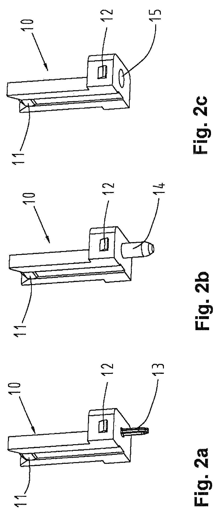
[0035]The first variation of the grounding contact 10 is illustrated in FIG. 2. This figure shows a massive metallic contact that is equipped with a press-in contact 13 in FIG. 2a, with a solder-in contact 14 in FIG. 2b and with a bore 15 in FIG. 2c.

[0036]The body shape indicates a slightly L-shape...


PUM


Abstract

In a board-edge connector designed for directly contacting a printed board includes a ground connection between the printed board and the connector which engages before the printed board is completely mated and connected to the voltage supply. A grounding contact is arranged in one of the corner regions within the plug-in slot of the printed board connector, wherein the grounding contact is connected to a grounding strip on the printed board on which the printed board connector is fixed. During the mating process, the printed board, onto which a grounding strip is applied on at least one of the lateral edges within the mating region, slides past the grounding contact such that an electrostatic equalization between the printed board to be newly inserted and the connector takes place before the contacting of the remaining electric contacts.

Description

BACKGROUND OF THE INVENTION[0001]1. Field of the Invention[0002]The invention pertains to a printed board connector, particularly a board-edge connector, with a plug-in slot, in which electric contact elements for directly pluggable printed boards are arranged.[0003]A connector of this type is required in order to ensure a safe ground connection between the printed board and the connector in addition to a mechanically exact guidance of a printed board in a printed board connector.[0004]2. Description of the Related Art[0005]Various devices are known from the prior art for contacting a printed board with a connector in such a way that a potential equalization initially takes place during the mating process before the voltage supply of the printed board is realized.[0006]For example, printed boards are provided with locking mechanisms that de-activate the voltage supply before the connector is pulled out and only activate the voltage supply during the mating process by means of a micr...

Claims


Application Information

Patent Timeline
Patent Type & Authority Patents(United States)
IPC IPC(8): H01R12/00
CPCH01R13/6485H01R12/721
Inventor LUETTERMANN, DIETERPAPE, GUENTER
Owner HARTING ELECTRIC GMBH & CO KG
Learn More