Combustion-engined setting tool

a technology of combustion engine and setting tool, which is applied in the direction of manufacturing tools, nailing tools, machines/engines, etc., can solve the problems of reducing the energy efficiency of the combustion process, and achieve the effect of improving the separation of incoming air

Active Publication Date: 2007-02-13
HILTI AG
View PDF7 Cites 2 Cited by
  • Summary
  • Abstract
  • Description
  • Claims
  • Application Information

AI Technical Summary

Benefits of technology

[0010]It is advantageous when the combustion chamber is connected with the first tool opening by the inlet of the inlet / outlet valve arrangement in a first operational phase or position of the inlet / outlet valve arrangement, is closed in a second operational phase or position of the inlet / outlet valve arrangement, and is connected with the second tool opening by the outlet of the inlet / outlet valve arrangement in the third operational phase or position of the inlet / outlet valve arrangement. Thus, the combustion chamber is connectable with different environmental volumes during aspiration of the fresh air and during discharge of the flue gas, respectively. By separation of the operational phases or positions of the inlet / outlet valve arrangement according to the present invention, a clear separation of the incoming air from the outgoing flue gas is achieved. Advantageously, the inlet / outlet valve arrangement is formed as a shuttle valve.
[0011]Advantageously, the inlet / outlet valve arrangement includes a closure member for closing the inlet, a closure member for closing the outlet, and a closure member for closing a combustion chamber opening of the inlet / outlet valve arrangement, with the closing member for the combustion chamber opening being actuated by a press-on element of the setting tool. The foregoing measures insure a technically simple association of the operational phases of the inlet / outlet valve arrangement with the setting process.
[0012]The provision of a first channel for connecting the inlet of the inlet / outlet valve arrangement with the first tool opening and a second channel for connecting the outlet with the second tool opening permits to further improve separation of the incoming air from the flue gases that are removed from the setting tool.
[0013]Further, the provision of the second channel for connecting the outlet with the second tool opening prevents accumulation of the flue gases in the setting tool housing and an uncontrolled discharge of the flue gas.
[0015]It is advantageous when the second channel extends, at least regionwise, past the outlet of the setting tool. This permits to use so-called “jet effect” (as in injection pumps) which is produced by suction of the outlet and which improves the discharge of the flue gases in the second channel.

Problems solved by technology

This can result in contamination of the aspirated fresh air with the flue gas which can reduce the energy efficiency of the combustion process.

Method used


Image

  • Combustion-engined setting tool
  • Combustion-engined setting tool
  • Combustion-engined setting tool

Examples


Embodiment Construction

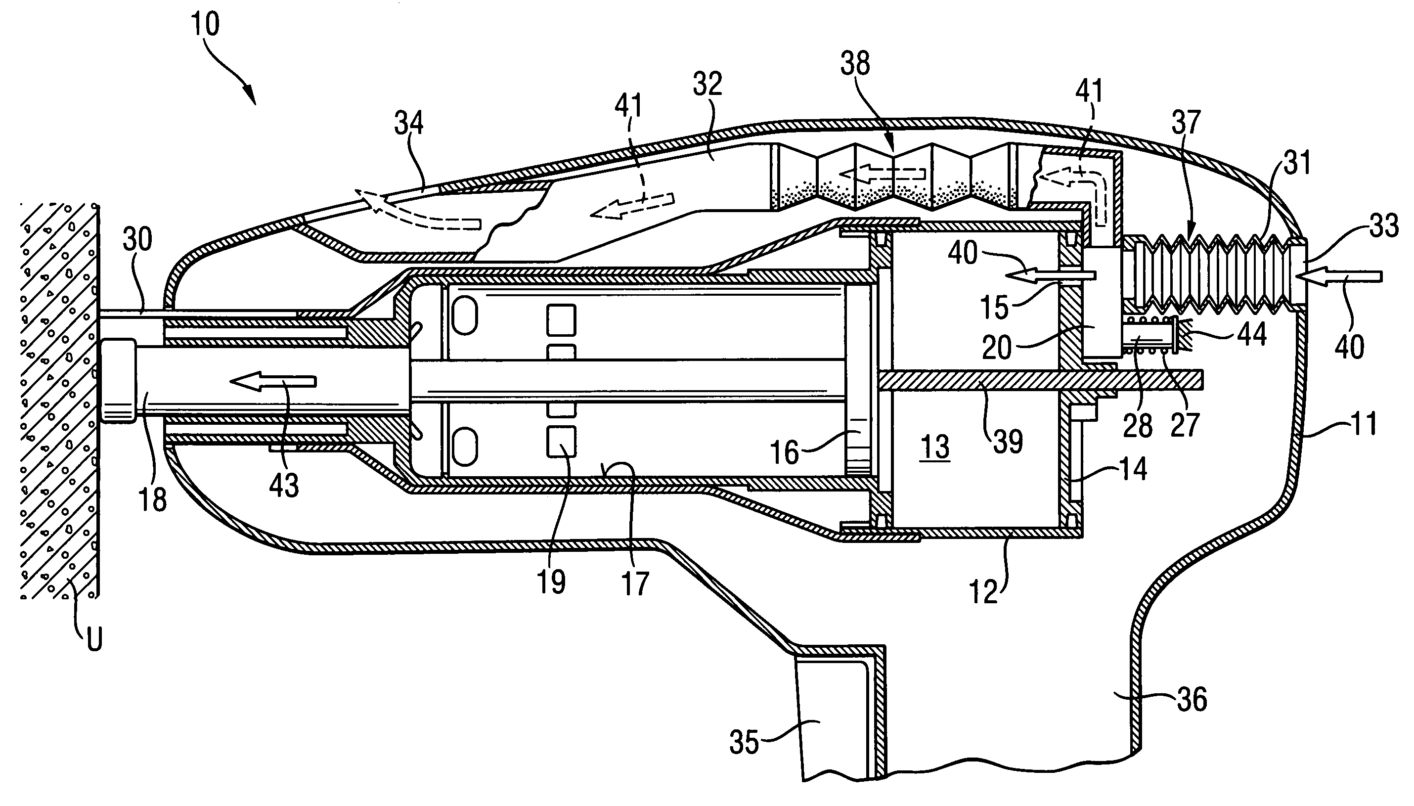
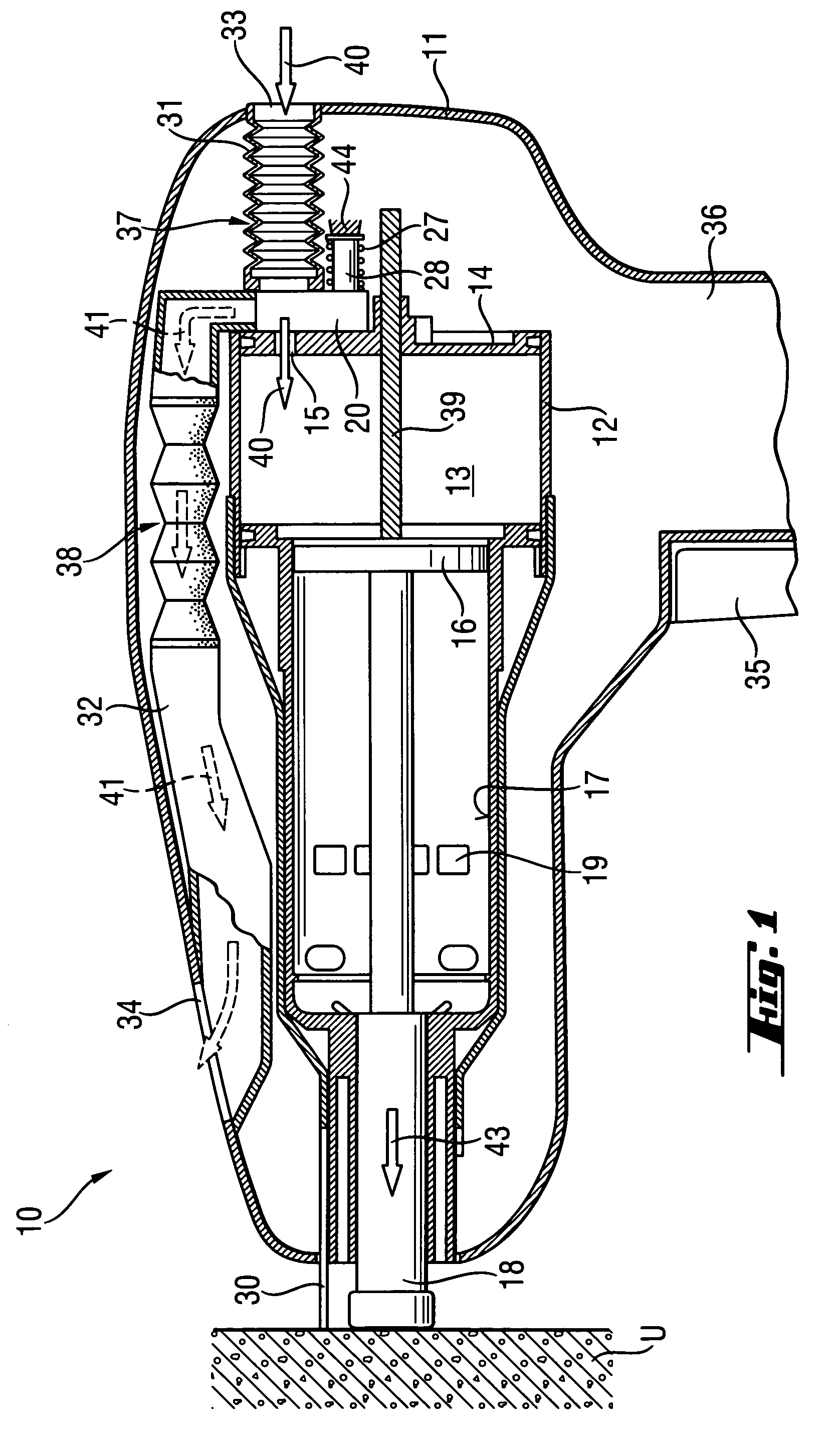
[0022]A setting tool 10 according to the present invention, which is shown in FIGS. 1–4, operates on a liquid or gaseous fluid which is stored in a fuel reservoir (not shown).

[0023]The setting tool 10 has a housing 11 in which there is arranged a setting mechanism with which a fastening element such as a nail, a bolt or the like can be driven in a constructional component U (FIGS. 2–5) when the setting tool 10 is pressed against the constructional component U and is actuated by an actuation switch 36 arranged on a handle 35 of the setting tool 10. The actuation switch 36 also actuates an ignition device (not shown), that ignites an air-fuel mixture contained in a combustion chamber 13.

[0024]The setting mechanism includes, among others, a combustion chamber casing 12 in which the combustion chamber 13 is expandable, a piston guide 17 in which a setting piston 16 is displaceably arranged, and a bolt guide 18 in which a fastening element can be displaced by setting direction end of the...


PUM


Abstract

A combustion-engined setting tool (10) for driving in fastening elements such as bolts, nails, and the like in a constructional components includes an inlet / outlet valve arrangement (20) that connects the combustion chamber (13) of the setting tool (10), which is filled with an air-fuel mixture, with at least two tool openings (33, 34), has an inlet (21) connectable with a first tool opening (33) and an outlet (22) connectable with the second tool opening (34).

Description

BACKGROUND OF THE INVENTION[0001]1. Field of the Invention[0002]The present invention relates to a combustion-engined setting tool for driving fastening elements such as nails, bolts, and the like in a constructional component and that includes a combustion chamber which is being filled with an air-fuel mixture, and an inlet / outlet valve arrangement that connects the combustion chamber with tool openings which communicate with the environment.[0003]2. Description of the Prior Art[0004]In setting tools described above, fuel, such as, e.g., fuel gas, is combusted with an environmental air in the combustion chamber. Before each setting process, fresh air should be fed into the combustion chamber, and after each setting process, flue gases, which are produced during a combustion process, should be expelled from the combustion chamber.[0005]In a conventional combustion-engined setting tool, such as Hilti GX 100 of the assignee herein, a setting piston is displaced in a piston guide that ...

Claims


Application Information

Patent Timeline
Patent Type & Authority Patents(United States)
IPC IPC(8): B25C1/04
CPCB25C1/08
Inventor HERTLEIN, PETERWOLF, IWANZAHNER, MARIO
Owner HILTI AG
Why Eureka
Try Eureka