Variable cycle propulsion system with mechanical transmission for a supersonic airplane

a technology of mechanical transmission and supersonic airplane, which is applied in the direction of machines/engines, vertical landing/take-off aircraft, aircraft navigation control, etc., can solve the problems of low airplane engine noise during takeoff, affecting the bulk and weight of the airplane, and the bypass ratio of varying designs cannot be good, so as to achieve the effect of reducing such drawbacks

Inactive Publication Date: 2002-12-19
SN DETUDE & DE CONSTR DE MOTEURS DAVIATION S N E C M A
View PDF0 Cites 14 Cited by
  • Summary
  • Abstract
  • Description
  • Claims
  • Application Information

AI Technical Summary

Benefits of technology

0012] The present invention thus seeks to mitigate such drawbacks by proposing a variable cycle propulsion system for supersonic airplanes which clearly separates the subsonic and supersonic configurations, in particular by using one or more separate auxiliary fans of large diameter.

Problems solved by technology

When designing a supersonic commercial airplane, there arises the particular problem of low airplane engine noise during takeoff, climbing, and landing.
Various variable cycle engine designs are known, however varying the bypass ratio of such designs does not enable optimization to be good, both in the subsonic configuration and in the supersonic configuration.
The propulsion assembly is constituted by retractable high-bypass ratio booster turbojets, and that presents numerous drawbacks, in particular concerning bulk and weight for the airplane.

Method used


Image

  • Variable cycle propulsion system with mechanical transmission for a supersonic airplane
  • Variable cycle propulsion system with mechanical transmission for a supersonic airplane
  • Variable cycle propulsion system with mechanical transmission for a supersonic airplane

Examples


first embodiment

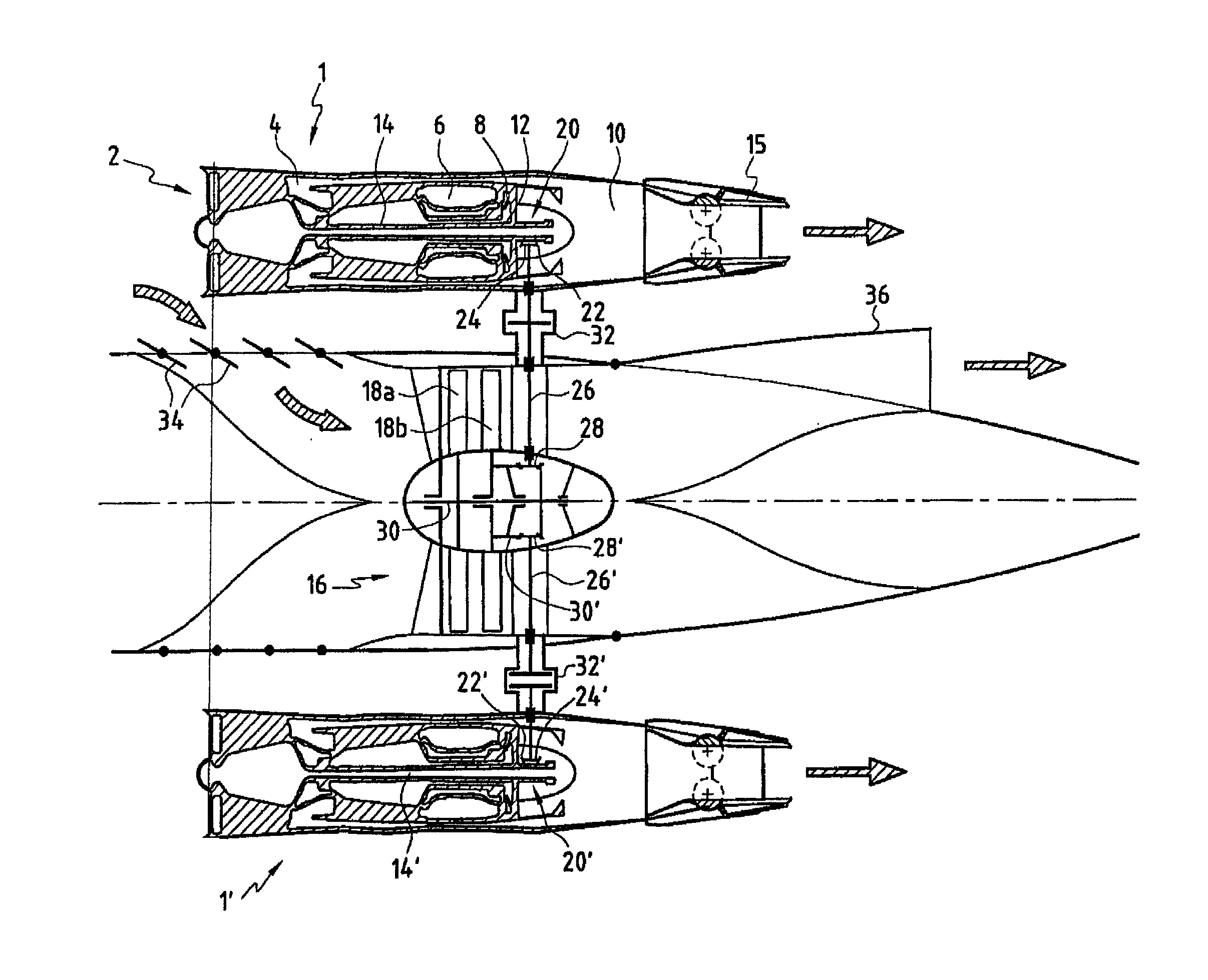
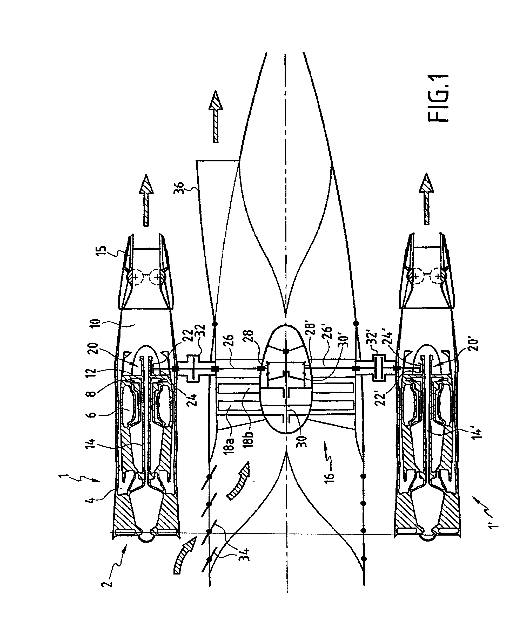
[0019] FIG. 1 is a diagrammatic longitudinal section view of a system constituting the invention, in which it can be seen that it is constituted in particular by two engines 1 and 1'. These engines are conventionally placed in pods (not shown) which are generally connected to the bottom faces of respective airplane wings.

[0020] In conventional manner, the engines can be of the single-flow type, having one, two, or three shafts, or of the double-flow type, having one, two, or three shafts. In this embodiment, each engine comprises an air intake 2, a compressor section 4, a combustion chamber 6, a high-pressure turbine 8, a section 10 for exhausting combustion gas, and a low-pressure turbine 12 which rotates a low-pressure shaft 14. Furthermore, the engines are dimensioned so as to be optimized for supersonic cruising flight (the period involving the longest flying time). The gas exhaust section is terminated by a nozzle 15 of variable section so as to be able to control the expansion...

second embodiment

[0031] In the invention (cf. FIG. 2), the propulsion system comprises two engines 1 and 1' independently controlling two auxiliary propulsion assemblies 16 and 16'.

[0032] As shown in FIG. 2, the fans 18a and 18b are each driven by a respective one of the engines 1 and 1' and they are housed separately in a rear portion of the airplane fuselage. For reasons of optimizing occupancy of the volume within the fuselage, it is possible for the fans to be offset one behind the other along the main axis of the airplane. In addition, closable louvers 34 are provided in the fuselage to enable the propulsion assemblies 16 and 16' to be fed with air, and deployable exhaust nozzles 36 enable that air to be exhausted in order to provide thrust during takeoff, landing, and subsonic cruising flight.

[0033] In the event of one of the propulsion assemblies failing, this embodiment makes it possible to continue driving the other auxiliary propulsion assembly.

[0034] Naturally, any other embodiment could ...


PUM


Abstract

A variable cycle propulsion system for a supersonic airplane comprises at least one engine capable of generating thrust for flight at supersonic speeds together with at least one auxiliary propulsion assembly that is separate from the engine and that is capable of generating additional thrust for takeoff, landing, and flight at subsonic speeds. The auxiliary propulsion assembly does not have a gas generator and means are provided for transmitting a fraction of the mechanical power produced by the engine to the auxiliary propulsion assembly in order to enable it to generate the additional thrust for takeoff, landing, and subsonic cruising flight. Means are provided for decoupling the mechanical transmission means for supersonic cruising flight.

Description

[0001] The present invention relates to a variable cycle propulsion system for a supersonic airplane making it possible firstly to obtain high thrust with a high bypass ratio during takeoff, landing, and subsonic cruising flight in order to greatly reduce noise during those stages of flight and to improve specific fuel consumption, and secondly to obtain a high exhaust speed adapted to supersonic cruising flight.[0002] More particularly, the invention relates to a propulsion system that has two different configurations: one configuration for takeoff, landing, and subsonic cruising flight; and another configuration for supersonic cruising flight.[0003] When designing a supersonic commercial airplane, there arises the particular problem of low airplane engine noise during takeoff, climbing, and landing. In order to be certified, all airplanes must nowadays comply with low noise regulations for takeoff and landing.[0004] Furthermore, supersonic airplane engines must also satisfy requir...

Claims


Application Information

Patent Timeline
Patent Type & Authority Applications(United States)
IPC IPC(8): F02C7/36B64C30/00F02K3/04F02K3/075F02K3/12
CPCF02C7/36Y02T50/671F02K3/12F02K3/04Y02T50/60
Inventor FRANCHET, MICHELLAUGIER, YANNLOISY, JEAN
Owner SN DETUDE & DE CONSTR DE MOTEURS DAVIATION S N E C M A
Why Eureka
Try Eureka